Yes that’s correct, good point and I meant to add this to the voltage sensor page. I need to do a pinout diagram of the RJ11 connector.
1 Like
Ok, I have been avoiding sorting this for a number of years but I think using the emontx4 to measure the incoming supply via an extension is the best solution.
I have emonpi on my house CU and solar, but another CU in the garage on a sub main and use a emontx3 for that (and evse) and sum the two for total use but it seems to have a margin of error to date I have not been able to eliminate.
They should change building regs to include conduit for CT clamps between meter cupboard and CU on new builds! Battery storage, hot water diversion, smart EV chargers for excess solar etc all need twisted pair to main supply usually.
1 Like
I second that - loads of pipes everywhere - capped so as not to become highways for mice.
1 Like
Still trying to finalise what CT clamps to order, can you pass two conductors through one CT? (Will go read the FAQ).
Yes, provided you want the phasor sum of the currents. In practice, that means both must be on the same phase, and pass through in the same direction (unless you want the difference rather than the sum).
Thanks, I have to say the reference docs are excellent these days much more comprehensive than they were back in 2015.
I just found it on the FAQ page:
You can pass more than one wire through the opening of a current transformer if you want the sum (more specifically, the vector sum) of the currents. There are two common instances where this is useful:
- You have a small current and it is difficult to get an accurate reading. In this case, the wire diameter is small. It’s possible to wind it into a coil and the C.T. can be fastened to the coil, or the wire can be passed though the CT opening several times in the same direction, effectively multiplying the current by the number of turns passing through the core. You can correct the reading by changing the calibration of that input.
- You have many small loads on different circuits, and you want to measure the total current used by those circuits. All the circuits must be on the same phase, and all the wires must pass through the CT in the same direction. If one wire passes through the CT in the opposite direction, the current in that wire will be subtracted from the total.
In my case, for reasons known only to the builders electrician, I have 3 ring circuits.
To enable monitoring of all loads on the rings it would help to pass the two adjacent rings through a single clamp and read both together, in this case they are same direction and phase should be summed.
Monitoring the cooker as a separate feed seems a lot more useful than having single feeds for each ring.
1 Like
Two possible reasons: First, the limit of 100 m² for the floor area served by one ring final sub-circuit, or it could be because of a desire to separate “essential” loads, like fridges, freezers, heating controls from circuits that might be more likely to have the protection tripped accidentally.
And I believe new regs, guidance, is to have the kitchen on its own ring,. thereby separating it from the rest of the house, and separating the high risk / most hazards appliances in the kitchen from the ‘house supplies’, where two rings feed front of house and rear of house to spread the risk.
Well it’s not square meterage issue, and the fridge and freezer are supposed to be on their own rcbo. I need to check if it really is kitchen only, it seems to be up/down for most of the house and the third ring is one side up and down, it’s weird.
I just realised that if I run an extension the emontx3 earmarked for the front door and meter cupboard could be repurposed at the main CU as well.
I need a spreadsheet at this rate to work it all out ![]()
That’s been the advice for some time - also because the kitchen tends to be where the highest loads congregate.
This seems to suggest a later addition to the original wiring. If the property was built or rewired when appliances weren’t quite so ubiquitous, it’s likely that there were a lot fewer socket outlets provided initially, and rather than rewire the entire house, it was simpler to add another circuit.
You would think so, but no this was all as built, only the solar and EVSE were added later. Have some time at home tomorrow, going to do some investigations and in the mean time compromise what CT I order with the emontx4 for most flexibility.
Trying not to clog up the thread with my personal situation but general observation for those reading later is that the clamp dimensions are in the shop on the Datasheet.
I have struggled in the past to add any more of the old YHDC clamps to the fuse board, and wondered if my ambitions to monitor as much as possible were a bit lofty.
I would advise anyone to check they have space before ordering, as having looked again this morning I will struggle to get either the multiple lighting circuits through a single CT as I hoped, or to add a lot of 50A size clamps.
It’s really tempting to one day change this board to a double height to allow much better arrangement of the circuits and some on rail modbus style meters, however it’s location in the downstairs WC brings a very high bar for WAF (Wife Acceptance Factor) that aside from the cost likely rules it out!
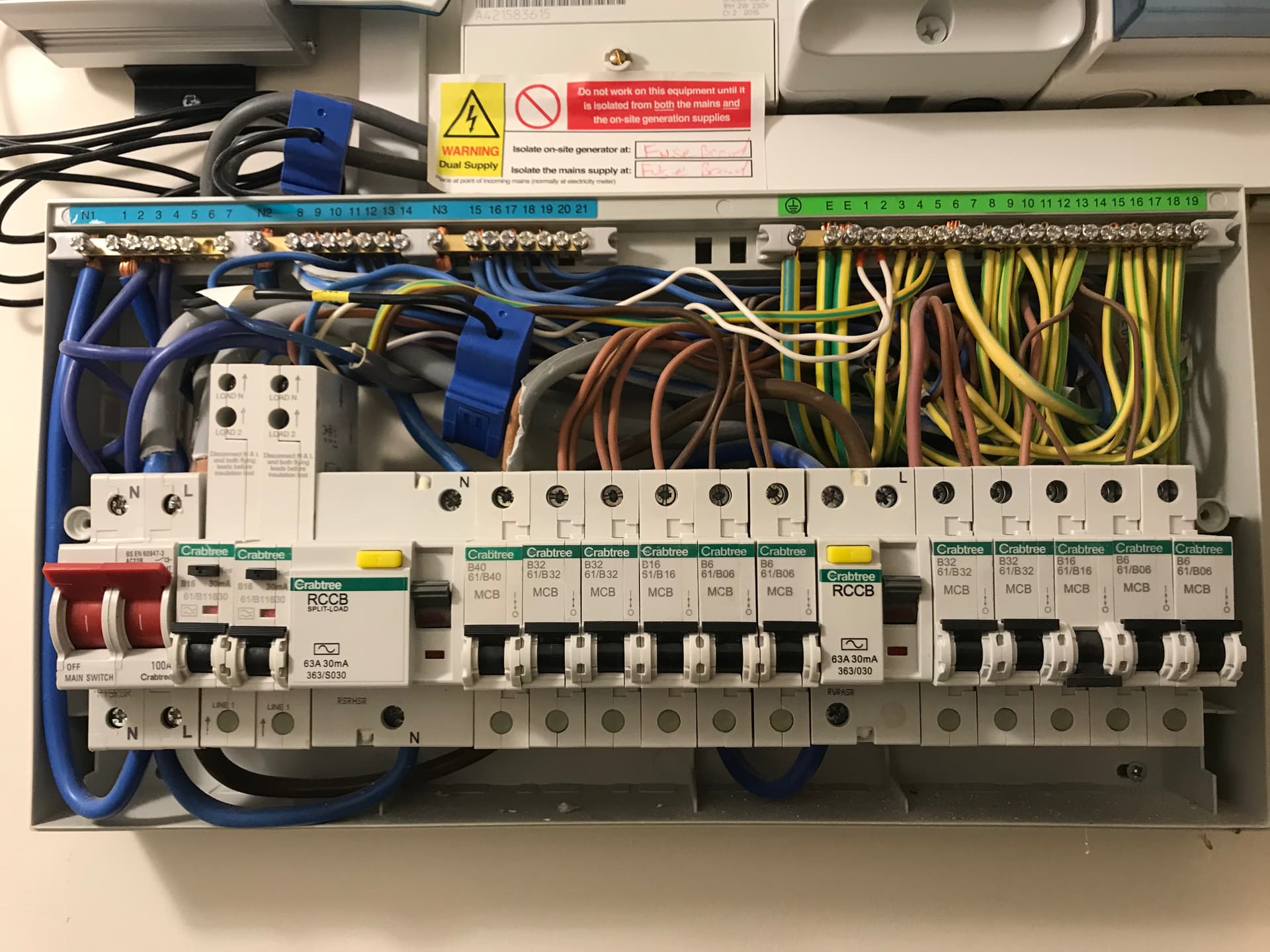
It’s a bit busy in there, mildly jealous of Glynn and Tristan’s layouts above with a nice sheet of ply to screw into and plenty of room around for tidy conduit!
Going with monitoring the 3 rings as that is where I’m leaking wastage at night, I know when the oven is on or off and I will try to pull the mic cable for the main supply through the house before ordering the expensive 100A CT later.
1 Like
The new Tx4/Vs/base combo is ideal for for the monitoring I need to do at the CU but I have a few ?s around what to get for the tank location.
It will involve several temperature measures, a CT on the HP’s control/pumps (an Ecodan powered via the outdoor unit), a connection to the Ecodan’s Sika flow meter, and ideally a way of connecting two Grundfos VFS flow meters that are on the solar thermal system but which the solar controller seems to be unable to get the right information from.
I think I need to get a second Tx as it will do most of this, presumably still limited to handling six DS18B20s (?) via an RJ45 breakout, and the Sika to one of the analogue inputs.
Does this Tx also need a voltage sensor for more accurate CT data or will the emonBase use the info from the one at the CU?
The VFS meters need a 5V supply, and create 4 analogue inputs – is it possible that one of the add-on boards could be a suitable base for these? Or a different board powered on the RJ45 chain? (I understand enought to see the possibilities, not enough to work them out unless it is blindingly clear!!)
Also, I tried adding a second Tx to my cart but it just duplicates the energy monitor set, but that’s the only way to get the emonVs so I can’t build it piece by piece. I’ll create a second order for the Tx only.
@whitecitadel that all sounds good, yes figuring our what can go where is always the challenge, especially with crowded consumer units which is usually the case. Im going to get an electrician to replace mine soon to get more room amongst some other work (battery & solar hopefully… ![]() ).
).
@NiHa It might be worth waiting out a bit for the best solution for the heat pump monitor. I will be documenting at least part of what you need hopefully later this week. It requires custom firmware so a bit of involved on that front, but if you are happy with that it’s fine.
There’s one analog input broken out to the terminal block on the outside of the emonTx4, then there are further analog inputs accessible internally, the CT breakout wont do what you are after so it would require some custom wiring to get more than one analog to work.
Yes it does require a voltage sensor, it’s doing a lot more than multiplying an rms voltage value with current, it’s sampling voltage and current many thousands of times per second in order to calculate real power so there’s no easy way to transmit that from the other emonTx.
Unfortunately it’s only 3.3V that is broken out on the emonTx4 (that’s getting changed in the next version). You could get the 5V from the emonVs, from the USB-C output or by connecting up your own cable to the 5V terminal block in the emonVs.
It should be possible to order multiple emonTx’s in the single order with different option sets. You need to add the first to the basket and then start again with the second. I’ve seen a couple of orders come in like that over the last few days so it seems to be working as far as I can tell.
Best of luck with the challenge of working this all out, Il update as soon as I’ve finished the heat pump build documentation discussing the use of the analog input.
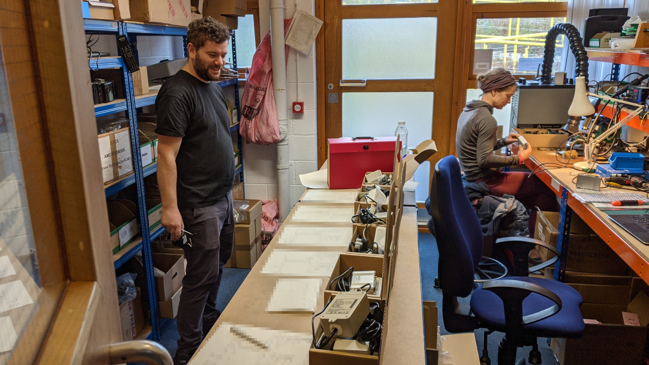
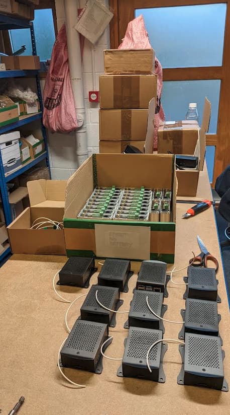
It’s been busy day in the office today getting the orders ready for shipping ![]() it was hands on deck for the whole team: @Gwil, Bella, @glyn.hudson and myself. The first few caught the post today, lots more to do over the next few days…
it was hands on deck for the whole team: @Gwil, Bella, @glyn.hudson and myself. The first few caught the post today, lots more to do over the next few days…
It’'s a great feeling getting a new design like this to this point. Thank you to everyone who has ordered and supported us, we really appreciate it!
2 Likes
3 posts were split to a new topic: EmonTX4 - use old or new kit
Latest updates to the documentation:
-
New structure to provide contained documentation for all the main OpenEnergyMonitor components including legacy hardware: https://docs.openenergymonitor.org
-
EmonTx4 documentation ‘docs’ part removed from the URL for a cleaner URL: https://docs.openenergymonitor.org/emontx4 Links updated in the shop and on this thread.
-
emonSD image release page moved into the new documentation site: https://docs.openenergymonitor.org/emonsd/download.html. Alongside documentation for EmonScripts. (UPDATED & includes new emonSD-10Nov22 release which is being shipped with hardware this week)
-
Emoncms user guide copied over from the guide: https://docs.openenergymonitor.org/emoncms/postingdata.html
-
A start on moving Learn into this single documentation location to try and provide a more integrated experience https://docs.openenergymonitor.org/electricity-monitoring/ac-power-theory/introduction.html#understanding-ac-power.
We’re going to move this to a https://docs.openenergymonitor.org subdomain. And ultimately redirect guide and learn once we are closer to finishing this process.
2 Likes
A new documentation page discussing the RFM69 radio packet format on the emonTx4 is now available:
Technical Guide — OpenEnergyMonitor 0.0.1 documentation
I will be added details about temperature sensing, RJ11 and RJ45 pinouts etc to this technical guide page. The intention is to integrate what we used to cover on the wiki on a single page here available directly in the guide.
1 Like
The documentation site is now available at https://docs.openenergymonitor.org/. The links above and shop page have been updated.
1 Like
Please can you do a global edit and get MHz right? Please, pretty please?
2 Likes