Yes so if you flip that over on the connector end, the RTS/RST & GND/GND pins will line up, then everything is correct. The programmer will appear to be upside down when connected but that is correct.
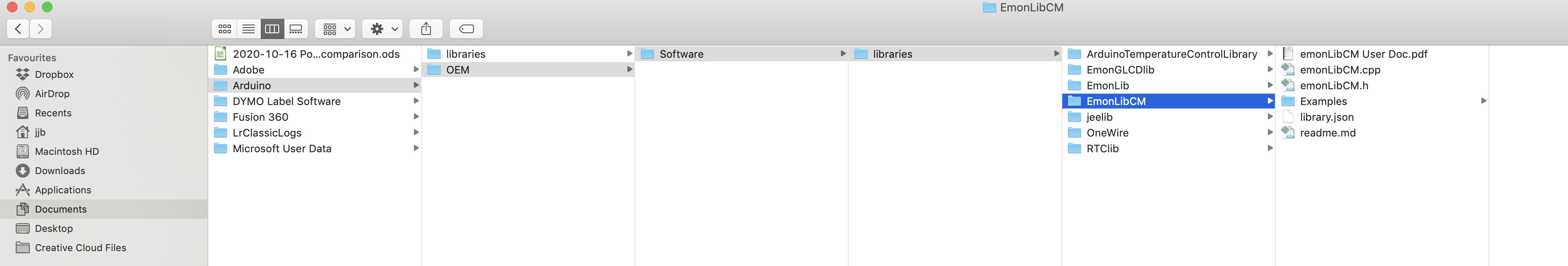
I have now downloaded the libraries, & moved them in to a new folder. I have told ArduinoIDE where this is. Within the sub folder Examples are EmonTxV34CM_max and EmonTxV34CM_min and EmonTxV34CM_min_RFM69. I have removed all underscores. The max and min folders only include one file each (.ino), but the 'RFM69` folder contains a .ino and an rfm.ino file. I can’t see a config though. So not sure which folder to use. (And I did shut down and re-start ArduinoIDE after making a file name changes.)
I did try to open the RFM.ino within ArduinoIDE and two panes showed, but not the third.
.

Those files you list are the example files that illustrate - as I hope the name of the directory they were in suggests, and if you’d read the documentation you’d have seen the explanation - the basic use and the use of every function of the library. You can compile and run them if you like, but they aren’t Trystan’s default sketch that’s loaded in the production emonTx’s. (And why did you change the names?) The file you want is the name I gave you:
It is on Github: GitHub - openenergymonitor/EmonTxV3CM: EmonTxV3 Continuous Monitoring Firmware (Default shipped EmonTxV3 firmware)
You need to put that under the “Sketchbook” directory - “…/OEM/Software” in your case. You need (due to a quirk in the Arduino logic) a sub-directory of [Sketchbook] called “EmonTxV3CM”, and in there you want EmonTxV3CM.ino, config.ino & rfm.ino.
Then open EmonTxV3CM.ino in the IDE. That’s where you should see what I described earlier.
Do you want to permanently remove the radio from your sketch, or use the w command when it’s running and you’re configuring and calibrating it? It’s just a case of removing with the editor 3 blocks of code that the logic removes if you turn the radio off.
Whichever way you do it, on the serial output (to the Arduino IDE monitor or eventually to the Pi Zero) you’ll get the data formatted for the EmonHubTx3eInterfacer - the format is “[name1]:[value1],[name2]:[value2]” etc. and you’ll get message no, voltage, upto 4 powers, upto 4 energies, upto 3 temperatures and pulse count. (Spelled out in lines 328 onwards in the main sketch file.)
Thanks @Robert.Wall . (I changed the names by removing the underscores as I had read that ArduinoIDE didn’t like underscores. But I will not do it again…)
I now have…
- A 3 pane ArduinoIDE, with
EmonTxV3CM §,config, andrfmshowing - A connection to the EmonTX via the programmer &
/dev/cu.SLAB_USBtoUART - A window with the inbuilt serial monitor (set to 115200 baud and “Both NL & CR” as mine doesn’t give an option for “Both CR & LF”) - this is showing scrolling text that “looks” about right, ie
ct1:0,ct2:0,ct3:0,ct4:0,vrms:515,pulse:0etc. - I can see the CT1, CT2 lines you referred to from line 328 etc.
But I have not altered the info in any of the three panes, nor uploaded anything yet. Before I did so I just wanted to check that all I now need to do is click on the 2nd icon (right arrow) within ArduinoIDE?
Also, should I specify the nodename before uploading the fw - perhaps in line 30 +/or line 31 +/or line 64? Or should I leave it as is and change it later within the emonPi’s emonCMS / Input.
FWIW, my current node names are 0, HWtank, Serial_PiZero_barn, emonpi, emontx2 (a rogue / unwanted Node), garage, house, and octopus so leaving it at “15” probably doesn’t matter?
EDITED TO ADD: I would be happy to remove the RF section now (but don’t know how to).
TIA
Julian
I was writing from memory - my laptop died and at that point, I hadn’t got the IDE set up on the replacement ![]() But you got the general idea.
But you got the general idea. ![]()
So it’s all looking OK so far.
This looks right for the “old”, non-CM sketch.
If you hit the button (the pop-up will say “Upload”), then it should compile and upload the sketch in one operation. You’ll see scrolling text in the bottom half of the window, the last 2 lines should say (but the numbers will be different - this is a different sketch in an old emonTx V2):
Sketch uses 3554 bytes (11%) of program storage space. Maximum is 32256 bytes.
Global variables use 367 bytes (17%) of dynamic memory, leaving 1681 bytes for local variables. Maximum is 2048 bytes.
If it fails, copy and paste the error messages (not a screenshot please). (You’ll have missed a library, or it can’t find it.)
And then the message - after it’s done the configuration and calibration text (just let it time out for now, you can always restart it and come back later to turn the radio off) - that you see in the monitor will change (if have nothing connected) to something like:
MSG:1,Vrms:361,P1:0,P2:0,P3:0,E1:0,E2:0, ... [etc] ... ,pulse:0
If you see that - maybe with some small numbers due to pickup, you have the CM sketch loaded and running.
Get the basic sketch working first. Let’s restrict ourselves to one problem at a time.
For reasons that I am not 100% clear about, but I managed to get rid of an error message
Global variables use 1299 bytes (63%) of dynamic memory, leaving 749 bytes for local variables. Maximum is 2048 bytes.
Invalid library found in /Users/jjb/Documents/Arduino/OEM/Software/libraries/EmonTxV3CM-master: no headers files (.h) found in /Users/jjb/Documents/Arduino/OEM/Software/libraries/EmonTxV3CM-master
by removing that folder from within the Arduino “tree” & re-starting the Upload, having read Compilation Error for 3phase sketch using PlatformIO and Visual Sudio Code - #11 by Patd37
But moving on, and wiring everything up, using Terminal I get this. It looks like this emonTx is now running EmonLibCM Continuous Monitoring V2.00, whereas it had been on emonTx V3.4 Discrete Sampling V3.10 . Perhaps that means a small “woo hoo” can be called? Or is the EEPROM error still something that needs addressing? Ditto RF?
EDITED TO ADD: Data is arriving on the emonPi EmonCMS too 
TIA
^[[Api@emonpi:sudo systemctl stop emonhub.service
pi@emonpi:~ $ miniterm /dev/ttyAMA0 115200
--- Miniterm on /dev/ttyAMA0  115200,8,N,1 ---
--- Quit: Ctrl+] | Menu: Ctrl+T | Help: Ctrl+T followed by Ctrl+H ---
emonTx V3.4 EmonLibCM Continuous Monitoring V2.00
OpenEnergyMonitor.org
ERROR EEPROM config contains 1 invalid values
Consider restoring defaults and re-applying config.
Loaded EEPROM config
Settings:
Group 210, Node 9, Band 433 MHz

Calibration:
vCal = 0.00
assumedV = 0.00
i1Cal = 0.00
i1Lead = 0.00
i2Cal = 0.00
i2Lead = 0.00
i3Cal = 0.00
i3Lead = 0.00
i4Cal = 0.00
i4Lead = 0.00
datalog = 9.96
pulses = 0
pulse period = 0
temp_enable = 0
Temperature Sensors found = 0 of 1
Temperature measurement is NOT enabled.

RF off
POST.....wait 10s
'+++' then [Enter] for config mode
NO CT's detected
AC present
MSG:1,Vrms:0.00,T1:0.00,T2:0.00,T3:0.00,pulse:0
MSG:2,Vrms:0.00,T1:0.00,T2:0.00,T3:0.00,pulse:0
1 Like
The reason is, as far as I’m aware, that is not a library. So it should never have been in the libraries directory in the first place. There are two distinct types of files used for two distinct purposes: library files, which are common components used across a range of sketches; and sketches themselves.
EmonTxV3CM is a sketch. emonLibCM is a library.
sounds like you’re right. ![]()
Yes - the EEPROM error is because the two sketches use the locations for different values.
Start up (use the reset button) your emonTx with the IDE connected and viewing the output, and wait for it to ask you for “+++[Enter]”.
Do that, and you should see the configuration and calibration options.
Available commands for config during start-up:
  b<n>      - set r.f. band n = a single numeral: 4 = 433MHz, 8 = 868MHz, 9 = 915MHz (may require hardware change)
  g<nnn>    - set Network Group  nnn - an integer (OEM default = 210)
  i<nn>     - set node ID i= an integer (standard node ids are 1..30)
  r         - restore sketch defaults
  s         - save config to EEPROM
  v         - show firmware version
  w<x>      - turn RFM Wireless data on or off:
           - x = 0 for OFF, x = 1 for ON, x = 2 for ON with whitening
  x         - exit and continue
  ?         - show this text again

Available commands only when running:
  k<x> <yy.y> <zz.z>
and then some more. You need to do this in two goes. First, choose r to restore the default calibration. That will wipe the EEPROM, the sketch will restart, find nothing (as distinct from stuff it thinks is wrong) and use the hard-coded default values. That includes turning the radio back on.
Go back into the config menu again with +++, this time do w0 to turn off the radio, then s to save.
If you do l [letter ‘ell’], it should list “sensible” numbers for the calibration values.
Finally, either do x and let it carry on without resetting, or to prove it can do it on its own, press the reset button again and let it time out and carry on.
If later you want to tweak the calibration, you know where to start.
If it is back on the Pi you can do this via miniterm.
Thank you so much, both @Robert.Wall and @borpin ; I now have two emonTx updated to the latest firmware and chatting happily to two Raspberry Pi Zero W’s which are both running emonSD_24Jul20. It will be interesting to see how robust the comms are in future compared with the ESP8266 widgets.
Your help & patience has been hugely welcomed, and if nothing else the next time my mother calls saying that she has removed the back of her (wired) mouse but can’t find any batteries to replace I promise to display a similar level of patience with her
I will hopefully go through the entire process again (twice) tomorrow as I switch the last pair of emonTx over to PiZeros. Fingers crossed  & I hope it is easier than these two have been!
1 Like
If you don’t mind, could you try the mechanism from the PiZero using Miniterm? It really should work.
I was reminded by @TrystanLea, that he has added the ability to do a TX via the admin interface. Designed to be done via a USB cable I think. However, looking through the code, it ultimately runs the same avrdude command we tried above - the rub being that we had to edit the script to change the pin number.
I therefore think that if you edit the file and change the pin number, you should be able to flash the TX from the admin interface and update it whenever necessary.
edit this file
sudo nano /opt/openenergymonitor/avrdude-rpi/autoreset
and change the Pin from 7 to 12.
#pin = 7
pin = 12
I’d advise doing an exact repeat of what you’ve done so far. You know it works.
Where is the fun in that - live a little - “nothing ventured, nothing gained”. If it doesn’t work easy enough to fall back to that but if it does then another tool in the toolbox. Bonus is that as and when you improve the CM firmware it is easily updated.
Brian, just take a step back and take in the overall view. We have a man who has been struggling with following your advice, now you’re suggesting that he gets confused again by doing something he knows was successful once a different way.
I shall repeat myself: I advise him to exactly repeat what he did the first time. We all know it worked.
Thanks dad.
The Inputs are coming through as P1, P2, P3, P4 and E1, E2, E3, E4, along with T1, T2 etc. All good so far, and the values “look about right”.
-
Previously I used to have processes such as
Log to feed, followed byPublish to MQTT, followed byPower to kWhon each ct#. Am I right to think that I would just add aLog to feedon the P1 and add aPower to kWhthe on E1 instead of both on each ct# (as above)? -
How do I prevent loosing cumulative data if the emonTx gets powered down for any reason?
-
And one more; and I know this is a bit back to front, but “why” does one need emonSD loaded & running on the Pi Zero at all? I always understood that the ESP8266 was just a “wifi dongle” and that it passed the EmonTx’s messages through effectively unaltered. So in that regard, what does the Pi bring other than comms?

One of 2 ways.
Note in both of these examples I am scaling the input figure that over reads compared to the meter and multiple logging for testing purposes.
On the Power Input use the Power to kWh process
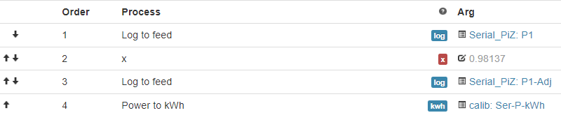
On the Cumulative Energy Input, the Wh Accumulator (I was testing the kWh Accumulator process and scaling the Input here)

Of the 2, logging the Power is least likely to reset during power off (it should auto correct).
1 Like
The PiZ brings
- An easier way to interface with the hardware
- More robust WiFi
- Multi distribution (send the data to as many servers by HTTP & MQTT within reason)
- In theory easier to update EmonTX
for basically the same cost.
You could just install and run emonhub on the PiZ with a RaspberryOS image, but you’d lose the UI to edit the config, update etc.
1 Like
Job Done! 
Well almost; I now have four EmonTx communicating to my emonPi via Raspberry Pi Zeros; I have recreated the Inputs & Feeds etc, just need to re-build my Dashboards and Apps now.
For future reference, I have attached a “How-To for Dummies” that I have cobbled together, in case it help others if they struggle as much as I do.
In hindsight, I found the process as fascinating as it was frustrating, but I have learnt a lot in the process. Words like sketch, Arduino, avrdude and miniterm are now familiar, even if what they do isn’t always …
2020-10-22 emonTx - Raspberry Pi Zero W.pdf (3.4 MB)
Once again, Thanks All for your patience !!!
1 Like
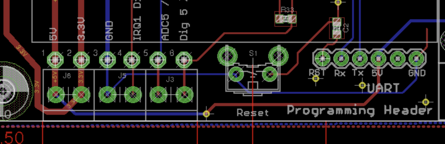
Looks good. I have just noticed on one of the photos, the internal serial breakout (JP3). You could have put a header on that and connected up so no external cable!