As most are probably going down the SMART Meter route? I have put together a Pi-Zero and MQTT client in Python 3 to register the reed pulse on Schlumberger R5 gas meter each time the pointer pass the 3pm to 6pm on Emoncms which I have been testing and works with 0.01 unit accuracy. If anyone is interested in this then let me know and I’ll put together a package to follow.
Hi David I have this meter smart meter people cant change it so I would like to know how you did it I have my emonpi right close to the meter. Many thanks Dave
This project worked on “Schlumberger R5 gas meter” not a SMART meter? As you can see the readings on the IHD unit normally. You can also use this site here https://energy.guylipman.com if you happen to be with Octopus.
Missed this post - would be useful - I tried and failed to do this.
I now have a ‘smart’ meter (which isn’t) so there isn’t a rotating dial any longer and only reports every 30mins to conserve battery.
I’m waiting on a GlowStick that does local MQTT data access although this will still not show instantaneous usage (see above) but at least I’ll know each half hour.
# import Libs
import paho.mqtt.client as mqtt
import time
import RPi.GPIO as GPIO


# set GPIO numbering mode and define input and output pins
GPIO.setmode(GPIO.BOARD)
GPIO.setup(16,GPIO.IN)

#set up a variable for reed activation
reed_state = 0

# set up counter Should be the reading on Gas meter including the smaller figure
# as this counts each 1 ft or M of gas used.
counter = 1151.60


def on_connect(client, userdata, flags, rc):
    print(f"Connected with result code {rc}")

def MQTT_Pub( counter ):
    client = mqtt.Client()
    client.on_connect = on_connect
    client.username_pw_set(username="emonpi",password="emonpimqtt2016")
# change IP to the one for the PI Zero W
    client.connect("192.168.0.105", 1883, 10)
    client.publish('emon/mynode/power1', payload = counter, qos=0, retain=False)
    client.disconnect()

try:
  while True:

    #check if reed newly activated

    if GPIO.input(16) == 1 and reed_state == 0:
        reed_state = 1
        counter=round(counter,2) + .01
    #pause to debounce
    time.sleep(.5)
    #check if reed released
    if GPIO.input(16) == 0 and reed_state == 1:
        reed_state = 0
        MQTT_Pub(counter)


#Close MMQT session & Clean up GPIO ports

finally:
  GPIO.cleanup()
As the link suggested. A Raspberry PI Zero W? I used one of the many GPIO pins that number is in the PHP code. The connection to the meter is via RJ11 which is connected on the underside counter unit. On the meter itself there is underneath an RJ11 which you should be able to feel running your finger beneath. The red pointer on meter took 1/4 turn to pulse on and off again. This is monitored via the GPIO of the PI Zero W and then registered via MTQQ client. If you watch the video the chap does the same with a press button.
Hope this explains enough. If not then let me know.
If you look at the numeric figures. Under the bottom of the plastic casing where the red numbers are you should feel the plug. It may have a plug in it which you may need to remove. (You need to get under it or take a picture with your phone of the underside of it. So, you are looking under the bottom of the plastic case. You should also be able to read under the numbers on the face off the meter. 12V d.c 10ma 1 pulse = 1ft. If this writing is not there, you many not have the plug.
There is a reed switch that is closes between 3 o-clock and 6 o-clock. I used a multi meter with continuity to find the wires that closed. I think they were the two outside ones. One is attached to the GRD pin on the separate Raspberry PI and the other is on the pin in the Php code. Pin 16. You will need to view the video to understand the way it’s connected. You will need the two resister as well. This will make it reliable. Otherwise, you may fry the GPIO port.
You are running this on a separate Raspberry PI zero that talks to the EMON PI via the WiFi network. As this then stops the system causing issues to the EMON PI. You can also then not worry when the EMON PI is updated with new software/firmware.
Hello David. Thanks for posting this. I have a Raspberry Pi model A that I could repurpose for reading my Schlumberger R5. just checked under my display and I have the RJ11 port, I made a quick YT short with my meter details removed to spread the knowledge. What are the resistor values did you use to take the 12v dc pulse down to something safe for the GPIO port of the pi?
My take on this was 29R2 = 11R1 so I think
R1 should be 470k and R2 18k
tracking the calculations back I make the resultant voltage to be 3.32v roughly.
checked my boxes of stuff and I already have the resistors, Pi and the RJ11 cable. this could be a no money metering solution. will then only have the water to measure after this for my home assistant instance but that isn’t even metered so there is nothing in the house to actually measure that yet.
DON’T run any voltage through the wires to R5. It as GAS meter and it will possibly explode if electric current is used. (Highly unlikely - but if you don’t have a house left after such event. Perhaps, we need to take the road of caution here). What you are testing for is if the GPIO pin is Grounding or not on the pin. That said. I followed this chaps diagram on YouTube here this also explains on bounce. Which, in the code has been taken care off. There is a video explaining the process. So, we are monitoring the closing of the reed which tends to happen from 15 min past the hour to 30mins pass the hour. So, in effect quite a long pulse. Hope this will help. The resister values are also specified on the website. If you need more. I have moved on to Smart meters now and use the Glow from Hildebrand (Not sponsored) This allow integration via MQTT and has an APP that provide usage last 10 seconds. PI is still monitoring the Solar and usage from that point. Cheers. :o)
Having supplied electrical equipment to the mining industry, I wrote a piece about Intrinsic Safety and gas meters for the old ‘Learn’ section. For anyone contemplating putting electricity in the vicinity of a gas meter, it might be worth tracking that down. [It’s under ‘Electricity Monitoring → Pulse Counting’]
And another word of caution: most equipment advertised as I.S. is actually only good for petrochemicals - the requirements for hydrogen or methane (in my case) are much more stringent.
Thanks David, yep being cautious I think.
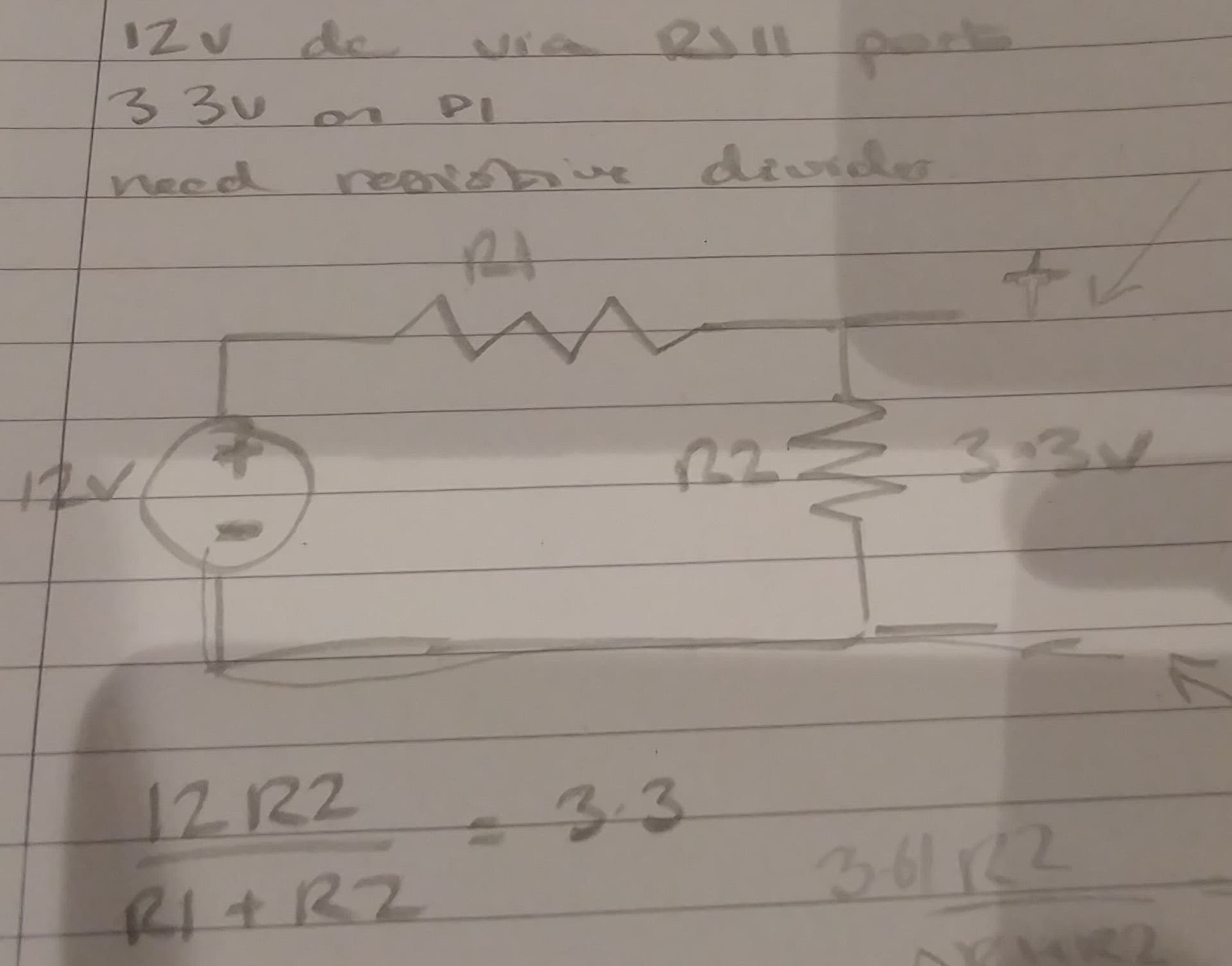
watched the video recommended and above is perhaps the slide most relevant.
my take away here is that I was barking up the wrong tree with idea of it needing a resistive divider however more questions have come to my mind.
The resistors required are the 10k pull down resistor and the current limiting 1k resistor between the pin16 set to input (in code) and the button/reed switch to 3.3v
is this not putting some current through the reed switch behind the rj11 socket in order to complete the circuit when the reed switch closes?
Also wrt continuity testing with a multi-meter for getting the correct wires of the rj11 cable, is that again not putting some small but not nothing current through the reed switch?
lastly why does the meter say 12V d.c 10ma on the meter if indeed it is only a reed switch passing a magnet underneath? is that the limits of current and voltage that should be kept below by any attached pulse monitoring equipment?
as a personal aside…
Frustratingly I cannot easily get my gas meter upgraded to a smart one since octopus’ outsourced minions partially botched my install. they came to do a joint electric and gas meter swap but only managed to commission an electric one on the second attempt/visit. The chap looked at my gas meter which at the time had two anaconda (bendy) pipes instead of one fixed and said he wasn’t happy swapping the gas meter over (which I very much empathise with if he felt it wasn’t safe or to regulations). After I had my gas engineer fix the house side of the meter to a solid pipe before the next octopus smart meter swap visit I was told that they had superseded the model of electric smart meter I now had had struggled to get commissioned and that the new electric meters were bigger and thus unlikely to fit on my electric cupboards’ board next to my consumer unit. They no longer has gas smart meters to match their own installed electric meter installed literally only weeks earlier. So I fear that I am quite out of luck to ever getting the gas metering made smart in this house but at least the Schlumberger R5 with the rj11 port seems very achievable with a careful considered approach.
Very happy to go slow and get this right before progressing any further. thanks for all your advices thus far.
I know that you are being careful. But, as this forum is open to the public we have to spell it out that anything over 3.3-5V @ 10ma is as much as should be pushed through this circuit. Otherwise, someone will no doubt fix up a 230VAC via the reed relay through the gas meter. That would be very dangerous and blow the reed in the process. The original connection is for the Gas DNO to fit a physical meter to which is normally has a plug fitted in the UK. But, not SEALED. If it were then we wouldn’t be doing it. Just like the sparks seal the electric supply. You are not suppose to break seals. Ok that said. In the time that I had this working 24/7 over several weeks it was in-sync with the meter reading. I live in a 1930’s house and the DNO connection was both shared and hadn’t been touched by the DNO since then. So, I also went through some pain with the swap to Smart Meters as the whole head had to be changed. But, it was worth it in the long run. I would set the system up with the PI away from the meter until you get it working by just touching the wires together. Then, attach to the G5 when you are certain everything is working as it should be. Don’t forget to change the Gas Meter reading in the code to what is on the meter. All numbers including the 10ths. Let me know how you get on. Cheers.
Make sure the wires to the meter long enough to allow for the PI and supply to be in a separate space outside of the GAS meter itself. Nothing but the low voltage wire running to the meter should be near the Gas meter. My PI-Zero was on the other side of a brick wall being powered. The cables can be 3-4 meters long with reasonable wire on the RJ11 plug. Such as the ones supplied by the Broadband crew. If there is ANY smell of Gas however slight then this project should be stopped and the Gas emergency line called to investigate. It’s the one service that does turn up normally the same day to ensure that explosion’s do not happen. Being able to read the Gas meter remotely is not worth losing your house or flat over.
Of course you must have current flowing to be able to measure a voltage - there is no practical instrument made that does not draw some current from the source you are measuring - and that is where I question David @Tagware and his understanding of electricity. Perhaps more so, I would never trust an on-line video without knowing the credentials of the source. I haven’t watched that video and have no time to do so.
That will be the maximum current and voltage that the internal switch is rated for.
I think the fact that there is a reed switch and rj11 port there means that it has been designed to be read by some external electronic monitor. Perhaps the prudent approach is to make a completely isolated bench testable setup first with its own similarly rated reed switch and test the code and hardware before using it on the gas meter. The video is basically a primer for gpios inputs using buttons and reed switches dealing as well with issues of debouncing to avoid repeated reads.
I think David has been careful in his own setup, I will do my own research into the resistor values required to limit current to a safe level. Failing all of this there is the alternate mechanism using an espcam to literally read the numeric values from the front of the meter.
Thanks for your input here, the clarification on the 12vdc 10ma is helpful.
Robert, it has been made clear that this uses electricity! 3.3-5v @ 10ma which is well below the rated reed performance. If you can’t be bothered to watch the video. Then, I suggest you can’t be bothered period to keep commenting. Nobody asked for your input. I certainly didn’t. Being insulting about if someone understands about electricity does credit you in being right. It just make look like a p****. Have a nice day.