Autometers DDSD285 Smart Meter Modbus RS485 interfacing and monitoring

Hi,

This is my first post after lots and lots of Google Fu trying to work out if/how to connect a Autometers DDSD285 Modbus Smartmeter for monitoring.

It is a very capable meter but as a non expert this seems a little daunting. I can see various RS485 connected devices but was hoping someone had already connected these devices for monitoring.
We have 3 of these units in different buildings. All building are on the same WiFi lan. Our plan was to use Low Power Rpi Devices at each meter connected via a usb to RS485 adaptor into each meter. The RpIā€™s would be connected via WiFi to the lan. Ideally we would collect the data from each device or have it send the data to our intranet periodically every n secs/minutes/hours etc.

Does anyone have any experience of using these devices and talking to them using the modbus RTU protocol. Really looking for a How to guide please.

This is the meter: https://www.bellflowsystems.co.uk/files/attachments/4906/DDSD-285-Brochure.pdf

Cheers
Tony

Do you have any info on the Modbus registers? I had a quick look but didnā€™t find the info online, perhaps it came in hardcopy with the meter(s)?

Although I have no experience of this particular meter, at the tail end of last year I was writing a universal script to capture data from a number of other Modbus meters. I didnā€™t have any specific difficulties with any of them, but they do seem to differ dramatically in their registers/addresses and to some degree how the Modbus is used/implemented. Iā€™m confident that with the Modbus register info it would be fairly straight forward to read the meter data.

There is some Modbus implementation in the emonpi variant of emonHub, but I do not know how flexible/universal that is, Iā€™ve not used it myself. Whether you use emonhub or something else (nodered?) to get the data into emoncms or another database (influx etc?) it shouldnā€™t be difficult once you have read the data.

You could do as you suggest and use one Pi per meter or if the meters (buildings) are close you might want to consider using just one, the rs485 connections allow devices to span up to 1.2km, so you could possibly remove the wifi link too if you wanted to run directly to a place with an Ethernet port. Less moving parts to maintain (go wrong), less power consumption and all managed via one log-in.

Hello Paul,

Thank you for responding. Not possible to run the cable between the buildings it would be much more preferable to run the emonpi/base OOB implementation as a starting point. Each can simply connect to the LAN via built in wifi and collect and post data . Really looks like a great platform. I found some info on the emonhub page around interfacers but there are none for Modbus RTU and none I can find for my Autometers DDSD285 device. IT seems that minimalmodbus library might help.

I found this article Read the SDM220 modbus with the minimalmodbus python module - #3 by Joaquin_Lopez but was a little confused by it. The ideal would be have a ā€˜standardā€™ interfacer for emonhub which would read the various registers in the meter and post these to emoncms locally and send the data to our hosted emoncms. Each meter point would be a node. We have a main one we plan to monitor the total grid feed statistics and then the others would be on the remote units in the other buildings. We can then use this data for internal cost centre etc.

I have uploaded the latest protocol guide from the supplier.

Autometers Modbus Protocol v6_3_23.pdf (851.4 KB)

I hope this makes sense. Currently waiting for the USB to 485 adaptor to arrive. https://www.amazon.co.uk/gp/product/B01N3LM0PU/ref=ppx_yo_dt_b_asin_title_o00__o00_s00?ie=UTF8&psc=1

Hopefully this should connect directly to the meter using a piece of CAT5e cable. Connections are simple 23 - TX Plus and 24 - TX Minus canā€™t find a ground so I guess just 2 wire connection.

Any help appreciated and thank you again for responding. I canā€™t believe that other people would not want this type of sensor data. We can monitor a lot of parameters from this meter it seems.

Another thought line was if we only needed a low power device at each meter station that could run python or other libraries to retrieve the data using mimimalmodbus periodically and simpy post that data to our central emoncms platform using curl or other method.

We would only need a Pi Zero W or something similar running a very basic setup.

Cheers
Tony

Hi Anthony,

Sounds like Modbus TCP is what youā€™re after. Essentially, itā€™s Modbus RTU in a TCP wrapper.

There is also a variant referred to as Modbus RTU over TCP.
The difference between the two (ModbusTCP vice ModbusRTU over TCP) is very small.

More info about both, here: About Modbus TCP | Simply Modbus Software

I took a look at the protocol document you attached to your post. The relevant info you want is
on page 48. i.e. the register map.

Bill,

Many thanks. There is no TCP, the cat5 cable is only for the 2 wires connected using RS485 Modbus RTU as the spec for the device says to use a piece of shielded TP cable. So we will simply use a pair from the CAT5e a a short cable between the meter and the pi.

Many thanks
Tony

You mentioned a Wi-Fi network, hence ModbusTCP.

You mentioned the post about reading an SDM220 meter was confusing.

Which part are you having difficulty with?

The devices will be connected to our LAN wifi. WE would need to retrieve the data from the DDSD285 using RS485 connected to a USB adaptor in the pi. I may be a little confused by all of this.

It seemed that if there was an interfacer for emonhub that would talk tot he DDSD285 using Modbus RTU via RS485 that would solve the problem and allow me to simply retrieve the data we wanted to monitor and post it into emoncms locally or remotely as per your post.

Itā€™s quite easy actually. To send the data to your local emonCMS, all you need to do is edit this line:
http://emoncms.org/input/post.json?node=1&csv=$GENW,$NETC&apikey=xxxxxxxxxxxxxxxxxxxxxxxxxxxxxxxx" > /dev/null

to read

http://your-emonpi-ip-address-goes-here/input/post.json?node=1&csv=$GENW,$NETC&apikey=xxxxxxxxxxxxxxxxxxxxxxxxxxxxxxxx" > /dev/null

I am just starting out and am very inexperienced with programming etc. My usage of the various terms should not imply any real understanding. The protocol guide may as well be in Russian hieroglyphics to me :slight_smile:

Cheers
Tony

NOT a problem. Everyone here had to start someplace, so being a newbie is OK. :grin:

As Paul (PB66) mentioned earlier, A Python script reads the data from the meter.
Thatā€™s where the bulk of the ā€œworkā€ is done.

I used to run emonCMS, but havenā€™t for about 3 years, so the Python script I use reads
the meter as well as sends the data to an upstream conection.

Knowing a little Python would make things much easier for you, but you should still be able to
get it set up and running with some help. After all, thatā€™s what weā€™re here for. :wink:

Thatā€™s an under-statement!

Looking at the Modbus registers (section 6 of the pdf), there is an incredible amount of data that can be queried.

Indeed, thatā€™s pretty much what I was doing at the tail end of last year, although not specifically for emonhub (yet). I have very little to do with the emonpi variant of emonhub, but i did write the version that was derived from so my ultimate goal is to get it into emonhub oneday perhaps.

My current aim is to have a universal modbus rtu interfacer, an instance of which can be created for each Modbus/RS485 network(bus) and on each network each device would be a node. The code Iā€™m currently working on uses model templates to define the registers and payload structure etc, so you can have multiple nodes of the same or different models on one bus with minimal setup. As I discover more meters, I can add the templates to the code and make it more universal, itā€™s quite tricky to accomadate all options without actually having any knowledge of what quirks the next meter may bring.

rs485 is actually a 2 wire setup despite many devices specifying (perhaps even needing?) a ground, the rs485 protocol is engineered to work on the difference between the 2 lines rather than their potential to ground. The devices I have worked with are a mixed bag of 2 and 3 wire requirements, a couple of the 3 wire ones I have tested with just 2 wires and they have worked fine, but I canā€™t say Iā€™ve tested them all, I tend to just fit the ground if specified.

As a sidenote, The sheer amount of data that could be read from this meter reinforces my choice of approach to reading registers. There are generally 2 trains of thought on this, one is to read each register in turn, the other to read all the registers in one hit. I have found neither approach is ideal.

The first one is easier to define just the registers you want, but it is incredibly slow, the risk there is the value from the last read register is no longer relevant to the first read register as so much time has passed.

The latter can quickly grab loads of data in one hit so it retains valid association between values, but you can end up with a lot of data you have no interest in, plus with devices that have a lot of registers, it could be slower than necessary due to sheer bulk (if it doesnā€™t timeout!). I have opted for a series of blocks so you can get just the stuff you want, but as fast as possible eg registers 2 thru 20, 52 thru 64 (for example) would be much faster than getting just the registers you want one by one and also much faster than reading 2 thru 64. I also have a method of discarding values eg read registers 2 thru 20, but donā€™t parse 10 is quicker than reading 2 thru 8 and 12 thru 20.

A brief scan through the pdf seems to show the registers you will most likely want to access are floats rather than integers/longs plus a scaling factor, that can simplify things somewhat.

One minor advantage to NOT having the 3 meters on one bus, is that it saves you having to change the idā€™s of 2 of them, they will probably all currently be id1, which is fine if they are on separate networks.

It can actually be a two or a four-wire setup. Depends on the hardware.

The point to keep in mind here is not so much one of earthing, but one of bonding.
Itā€™s important to make sure all of the devices involved are connected together.

More info here: AN031.pdf (197.5 KB)

From the pdf file:

it functions as the ā€œsignal referenceā€ for the RS-485 receiver circuitry. While RS-485 uses a differential voltage signal, material physics requires it to still reference those voltages to itā€™s power supply earth. So while in theory an RS-485 receiver should see no difference between an input data signal of 1v and 4v (3v differential signal) and an input data signal of 1001v and 1004v, material physics (and common sense) says that the 1001v & 1004v data signal will not result in effective RS-485 data communications! So we need the 3rd ground wire to force our receiver circuit to reference the same ground as the transmitter used to generate the voltage. The EIA/RS-485 standard requires the voltage of the 2 receiver pins of the interface chip to be less than Ā±25v with reference to the chip ground. The rdcLPU design guarantees that the Di+ and Di- terminals remain within Ā±15v with reference to the earth/surge ground. So running the 3rd ground wire from the SGnd terminal of the rdc485ic to the SGnd terminal of the rdcLPU guarantees that the receiver pins of the RS-485 chip will remain within Ā±15v with reference to the isolated circuit ground within the rdc485ic.

The majority of meters (all of the ones I have encountered thus far) are all half-duplex, I think full-duplex rs485 is becoming a rare breed these days, certainly in the devices we are likely to encounter here.

Fair enough. But you said

With no mention of meters. i.e. a generic statement, if you will. :wink:

Paul,

Many thanks. Yes the idea of a template per device is what I was expecting. So that each device e.g. my DDSD285 would have parameters configured to collect and transform the raw data into usable KWh Total Amps etc.

I can see that in the protocol guide there are registers for both single and 3 phase power. They make other devices that are 3 phase.

The data it seems is in reasonable contiguous blocks Voltage - 30017 to

We are looking at monitoring :slight_smile:
Voltage
0x0010 30017 4 Voltage L1 R Float V
0x0016 30023 4 Voltage Max L1 R Float V
0x001C 30029 4 Voltage Min L1 R Float V
0x004E 30079 4 Frequency R Float Hz

Plus Current and Power etc. it seems that there are various data type used like Float, 16 bit MIns, Secs, EPOCH etc. The units should fiot into the emonhub schema to interpret the data correctly.

If someone could show me the basics or you could share your template structure with a few examples I am happy to enter all the parameters from the protocol guide.

We probably donā€™t need anything as heavy as emonpi on the meter nodes. Just something that can talk to the meter, collect the data and transform it into usable data we can then send to a centralised hosted emoncms to log it and present it.

Also each device is locked as ID1. They only cost 20 GBP each. But that should not matter as each would be an island of data and would talk to its DDSD285 independant of any other DDSD285. Each would not see or know about the other as each is connecting via a discrete meter. The connection to the central emoncms would post to its own feed identifier e.g. Main Grid, Building 1 etc.

Found this:

This seems to be defining the various datatypes and registers and seems to be reading big blocks as per your conclusion.

If this was for the DDSD285 then I guess it could be run via systemd as a service every n secs/mins etc. The output sent to emoncms. Again I may have fundamentally misunderstood so please forgive my ignorance.

Cheers
Tony

In general terms, to get Modbus type data off a device, Iā€™ve used an USB RS485 device, plugged into an OrangePiZero, which then sends the data over the LAN via MQTT to emoncms. If you need wireless the OPi zero WiFi is not the best so Iā€™d use a PiZero or an Esp 8266 device.

Paul,

Can you share your code and any example templates. Just trying to get my head around this and separate out the various TODO items.

In block terms and ideal world. There would be a standard interfacer in emonhub that could accept data from the DDSD285 (does this mean firmware needs to be written?)

DDSD285 - RS485 - USB - standard Rpi running emonpi/base software
Some kind of interface script to interrogate the DDSD285 and retrieve the data
transform/format the data and send to ??? (emoncms ?, emonhub ?) locally and/or remotely.

I think I might be confusing a lot of things here. emonpi is designed for CT monitoring. TI seems that it needs a node for RS485 Modbus with some kind of template selectable for the target device e.g. DDSD285. Then data would then be available and consumed in emoncms as the CT derived data is today.

I am not sure where to start with the above.

My adaptor arrives tomorrow so I can start to communicate with the DDSD285. I am also confused about a resistor that is mentioned in various documents and can be software enabled/disabled in teh DDSD285 I donā€™t know about the USB to RS485 adaptor. As there will be only one device on the RS485 MOdbus is this required? Do I need to tell the DDSD285 to enable or disable the resistor and if so how can I connect to it if this needs to happen as I will have a usb to RS485 adator
https://www.amazon.co.uk/gp/product/B01N3LM0PU/ref=ppx_yo_dt_b_asin_title_o00__o00_s00?ie=UTF8&psc=1

A piece of Cat5e connected using a single par into 23&24 on the DDSD275 and A&B on the adaptor.

Do I need any other hardware?

Cheers
Tony

Just a note. I have had a couple of these USB devices and they are not particularly robust and fail quite regularly IME. However, I do still use them as there is little alternative.

Iā€™m certainly not opposed to sharing code, but I havenā€™t got anything in a finished state to give you. As I said, I was doing this late last year, unfortunately, things got a bit crazy towards xmas and I havenā€™t yet got back to it. When I had to put it aside I was in the process of changing it to accept read values for scale factors as well as defined fixed scale factors.

Iā€™m always wary of releasing stuff before itā€™s fully tested as you become committed to using stuff you wish you had done differently. So whilst Iā€™m not ready to release a finished script, I am willing to share ideas and code and you can do what you wish with it.

You certainly donā€™t want to run before you can walk, so as previously said, if you(we) focus on reading the device, then passing the parsed data onwards is a relatively small addition (depending on what youā€™re aiming for of course). Yes it would be good to see it as an emonhub interfacer, but that cannot be your initial ambition. I always start out with a python script posting to emonhub via a socket interfacer, then work towards an interfacer from there.

I will try and post some stuff here in the coming days, but right now I think I think Iā€™m on the brink of a cold, My throat feels like Iā€™ve eaten my own weight in broken glass and Iā€™m starting to ache from head to toe, so Iā€™m not promising I can do this immediately, but I am overdue getting this back out on the bench, I also have a new heatmeter here I want to crack too.

Paul,

@Bill.Thomson

Many thanks. I sincerely hope you get well soon. I apologise if you felt I was pushing too hard. I do have some enthusiasm for this project and can see it as a useful addition to the emonhub concept. I admit I got a bit lost looking at how the emonpi CT data got into the emonhub interfacer. Seemed to revolve around some ā€˜firmwareā€™ files as this product is based on an ATMEGA board. In our world we use standard Rpi devices and interface to external devices (meters, monitors etc.) using RS485 this would of course open up the platform to monitoring anything we could put on the Modbus. But to start as you say start simple I have one rpi talking to one Meter using a USB to RS485 adaptor.

I am pretty sure i have a handle on minimalmodbus.py to talk to my device. I will report back progress on this thread as I have now setup my ā€˜test rigā€™ consisting of a DDSD285 plugged into the mains and a extension bar plugged into the load side(currently powering the Pi and monitor etc.) A pair in the CAT5E into 23 & 24 and A&B on the adaptor.

Not sure you saw my note about the resistor, confused about this. I only have one device on the RS485 Modbus.


Cheers
Tony

I certainly didnā€™t aim to curtail your enthusiasm, you are absolutely right that an emonhub interfacer would be good. My comments were purely to defer that aspect whilst focusing on the reading of modbus and your device in particular. Often it is easy to end up with a less than great interface when your focus is spread across the whole route the data takes. There will be suggestions to use MQTT, nodered emonhub emoncms directly and all have their proā€™s and conā€™s. but the best approach is to get the best reader code up and running and then find the best way to get that reliable data to itā€™s destination, rather than trying to read the data in the best way to send by MQTT (to pick one at random).

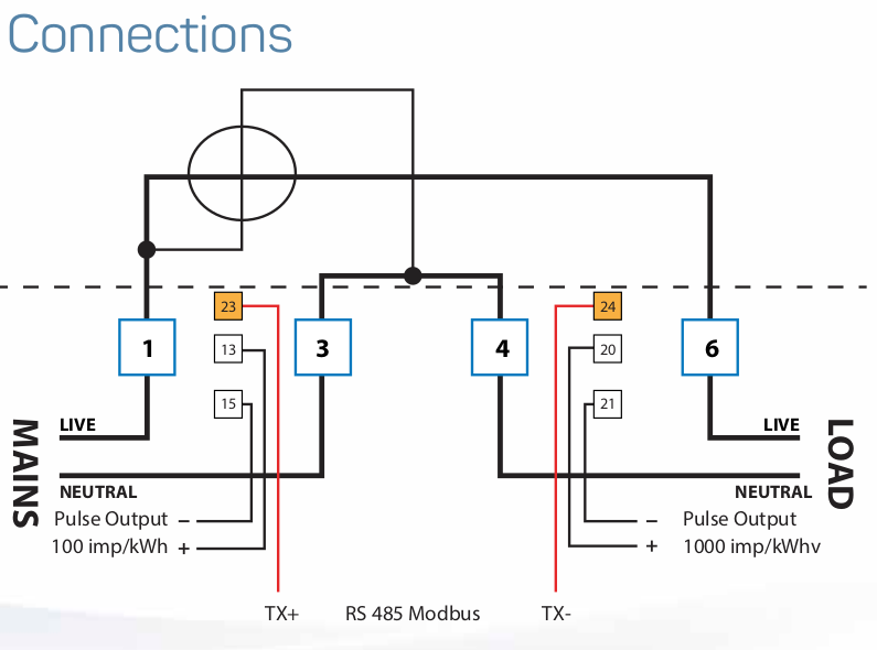
My heads a bit woolly today so sorry if Iā€™m not clear or get something wrong. AFAIK (without reading your docs pdf) a termination resister would only be needed if there were multiple devices on one bus and from what you say it sounds like there is a in-built resister that is connected by a setting, presumably with just one meter you shouldnā€™t need it, usually it would be the last meter in the chain that has a resister (inbuilt or added to the wiring across the 2 wires). But this can be checked in the docs, it will most likely be in there, just buried somewhere. Getting this bit wrong will not cause any damage, worse case scenario it will not work or work intermittently.

Cat 5e is ideal, at this point the worse you could do is get the 2 wires the wrong way round, again this will not cause damage, it simply wonā€™t work until you switch them. I only mention this as there have been instances where interpretation of A and B by some manufacturers has been at odds with the general practice, so the labels are not guaranteed to be right in absolutely every case.

If you are writing your own code, a couple of things to consider are, make each read short and reduce the timeout to a number that is adequate to read, with some wriggle room, hacving a 60s timeout on a 150millisecs read just delays moving on to the next read, if the device hasnā€™t responded in 200milis, itā€™s not going to respond in 60s. Also have a small pause between reads, this is another reason block reads are better as you can allow more settle time with fewer slower reads than rattling off many rapid single reads.

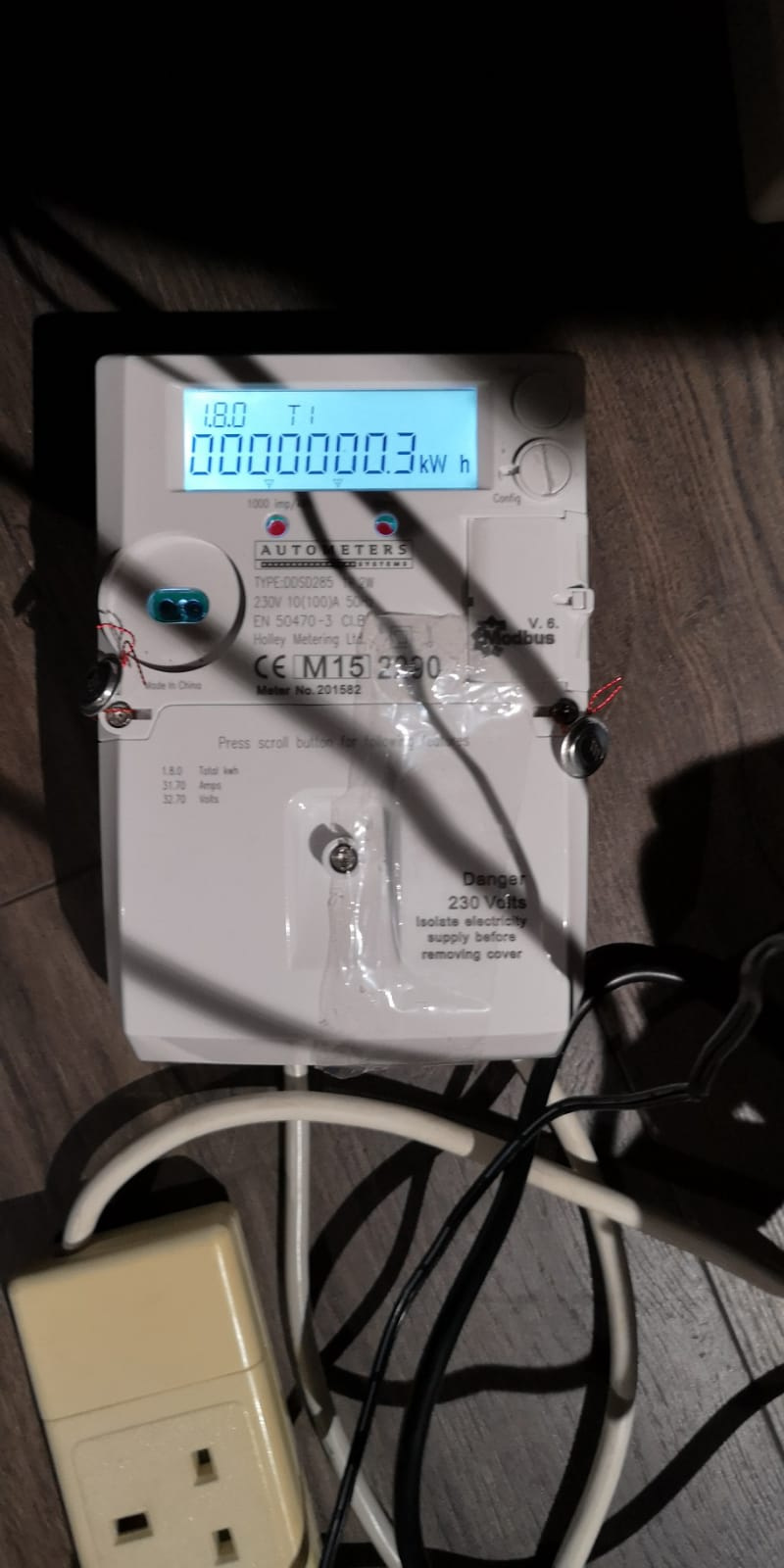
This device has raise a couple of thoughts regarding my aim for universal approach in that it is the same device for both single and 3ph installs, at this point Iā€™m inclined to have (at least) 2 templates eg ā€œDDSD285_1phā€ and ā€œDDSD285_3phā€ so that single phase users do not have to read/report 2 unused phases. A similar question remains about the size of the reported data, I have been lucky so far in that all the devices I have done, have had a limited number of reported values. This device has so many potential metrics to read that maybe we need ā€œbasicā€ and ā€œadvancedā€ templates too? Many users would only want to know the basic energy monitoring values and have little interest in what percentage of that consumption was up in the 24th harmonics (to pick one at random).

Users that have a Modbus network of half a dozen devices may not want it bogged down interrogating the indepth details of the energy supply rather than swiftly moving on to the gas meter or something else. This is where individual value reading come in handy, but IMO it doesnā€™t warrant the complexity and slow read rate inflicted on the bulk of the mainstream users to serve the few that want more info. This bit requires some further thought for any universal implementation, less so for a custom implementation specific to you.

The data read by the CTā€™s on a emonPi is indeed processed by the firmware on the ATmega328p and then it is passed via serial and the Piā€™s GPIO UART, this is then read by the ā€œEmonHubJeeInterfacerā€ in emonhub and passed via MQTT to local emoncms or HTTP(S) to a remote emoncms server.
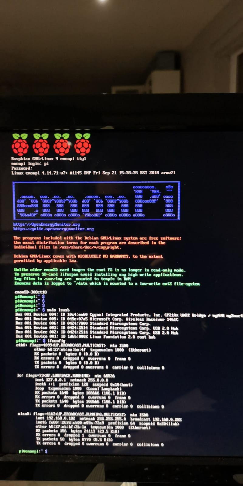
There is no additional ā€œfirmwareā€ involved with your Modbus reading. The Python script will read the Modbus via the rs485 adapter, seen as a serial device eg /dev/ttyUSB0 perhaps on your emonPi?

Initially we would look at the console output by simply including some print() statments in the script, then look at getting that data out to itā€™s destination once itā€™s right in the console.

You do not need to try and develop your script on the emonPi, Python will run on a windows machine too. If you want to develop on a PC first, you can then just edit the port from (for example) ā€œCOM7ā€ to ā€œ/dev/ttyUSB0ā€ when you move it over. I do all my deving on a full size PC initially as it is faster and easier than doing it via SSH on a RPi. But each to his own, what ever you are at home with.

Looking at something you said earlier about the slaveid being ā€œlocked as id1ā€, not that it matters much to you, but for my intended system to work there must be no ā€œid1ā€ on the network except when a new device is added until it is assigned another id (making room for the next new device), so I looked at your pdf and it appears the slaveid IS configurable it is register 31317 (page 70). Have you been told otherwise? or is you meter different? As a rule (in my experience so far) all Modbus devices (or maybe just meters?) start out life as id1, then they get set to a network unique id by the user.

Hopefully I will be back running on all cylinders again soon and be of more help too you, this isnā€™t even a proper cold, Iā€™ve had worse hangovers, Iā€™m just finding it impossible to concentrate or think straight at the moment, so forgive the waffle (more than usual).