Auto calibration with ADE9153A mSure

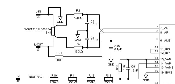
Intrigued by a recent post I’ve gathered some data on how self-calibration works on this device. As noted in that thread, the front-end of the shield sits at 230V - the GND of the IC is the Active of the grid, so great care is required if anyone else is planning to experiment. Here’s the relevant snippet from the shield’s schematic:

The only requirement for an mSure run is that the IC is powered. There’s no need for a voltage swing at the V inputs and there’s no need for a load to be drawing current, but it can (and typically does) work with both of those items present, so it’s pretty flexible. The only downside of an mSure run is that the device stops accumulating energy consumed during the run, so violates the measure-every-cycle rule.

Starting with the V channel, VAP and VAN are the differential inputs for the voltage “sensor” - a 1M/1k divider. VAMS is the mSure output signal used to calibrate the divider. When mSure is running, it injects a signal into the bottom of the divider, running the divider backwards, and compares that with the signal coming back through the differential inputs. The end result of an mSure run is a suggested fine-tune gain setting (from the default of x1) for the VAP/VAN input channel to compensate for variations in the divider resistors, but there are challenges.

The signal itself is a square wave with slow edges, moving between ~800mV and ~400mV. When you put 800mV into that divider backwards, you get back 799.992mV if the resistors are all perfectly precise. mSure is using what it gets back to determine the actual divider ratio so it’s working way down in the uVs to do that.

The second challenge is you need to complete the circuit for the injected VAMS signal. In the schematic above, the top of the divider is just floating at the Neutral pin of the meter. You could use a jumper to short the Neutral and Line-IN pins together to give mSure a very clean environment in which to measure, but more commonly you’ll have them connected to the grid. The grid resistance is infinitesimal compared to the 1M divider it’s in series with, so can be thought of as a jumper between Neutral and Line-IN with one important difference: the grid is now injecting its own signal into the top of the divider while mSure is injecting one in from the bottom.

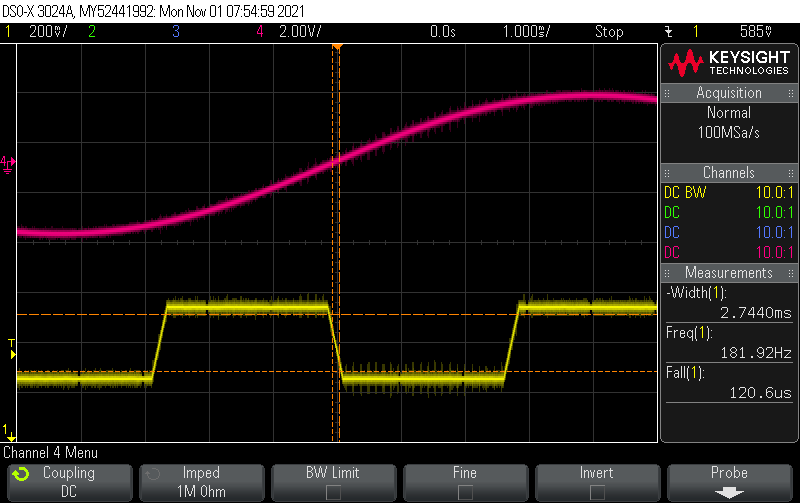
Below are captures of the divider output during an mSure run with different V swings on the Neutral / Line-IN pins:


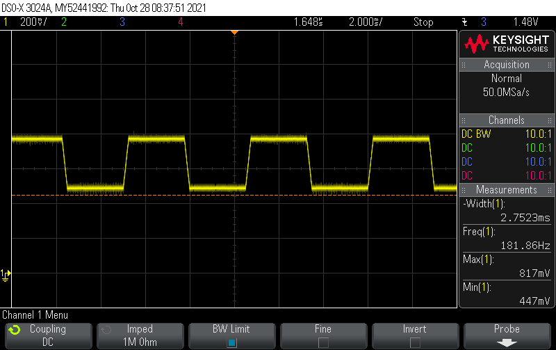
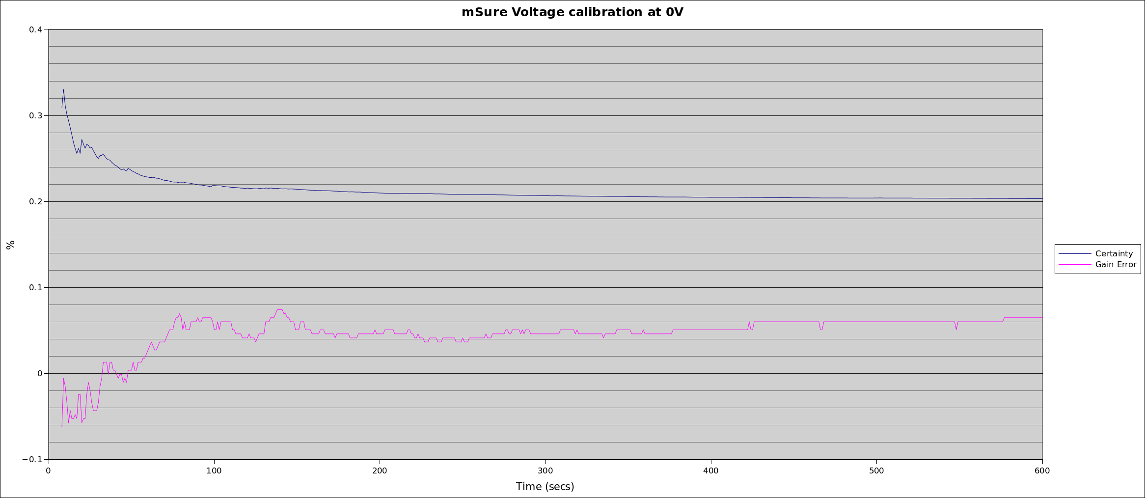
No AC swing (Neutral and Line-IN shorted together with a jumper)


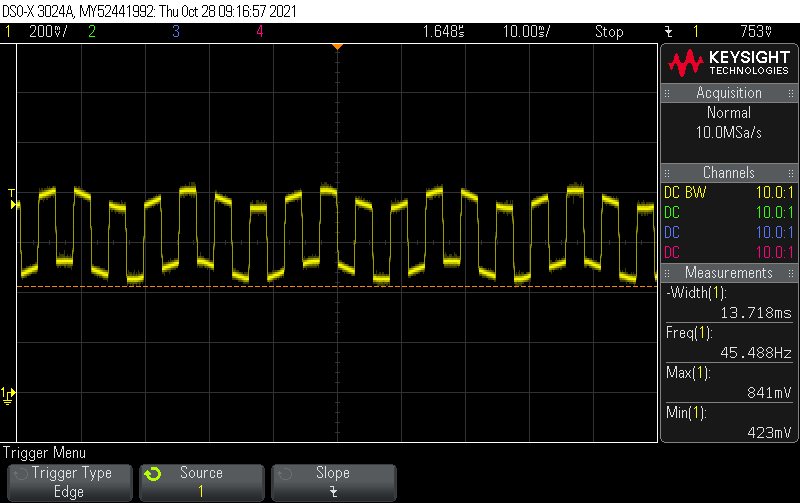
26V AC swing at Neutral / Line-IN


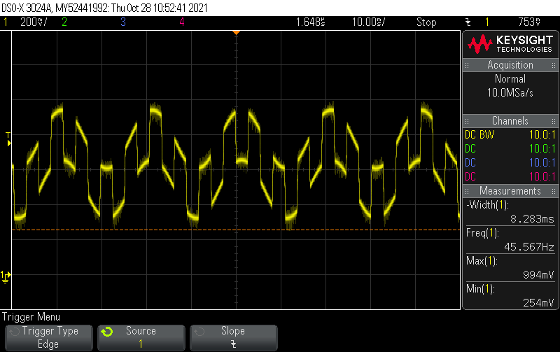
120V AC swing at Neutral / Line-IN


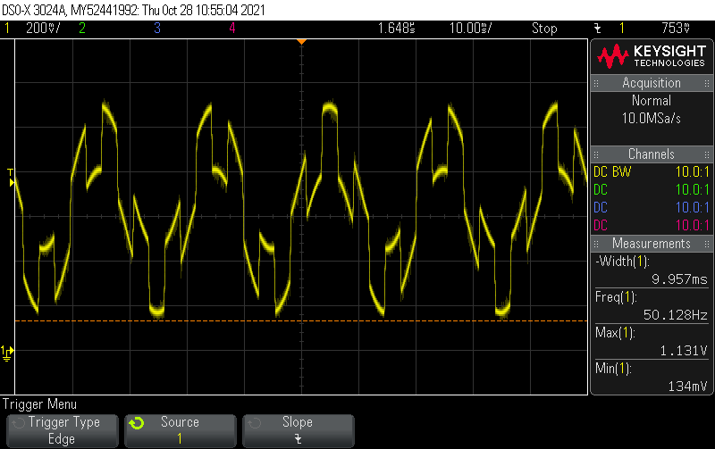
230V AC swing at Neutral / Line-IN

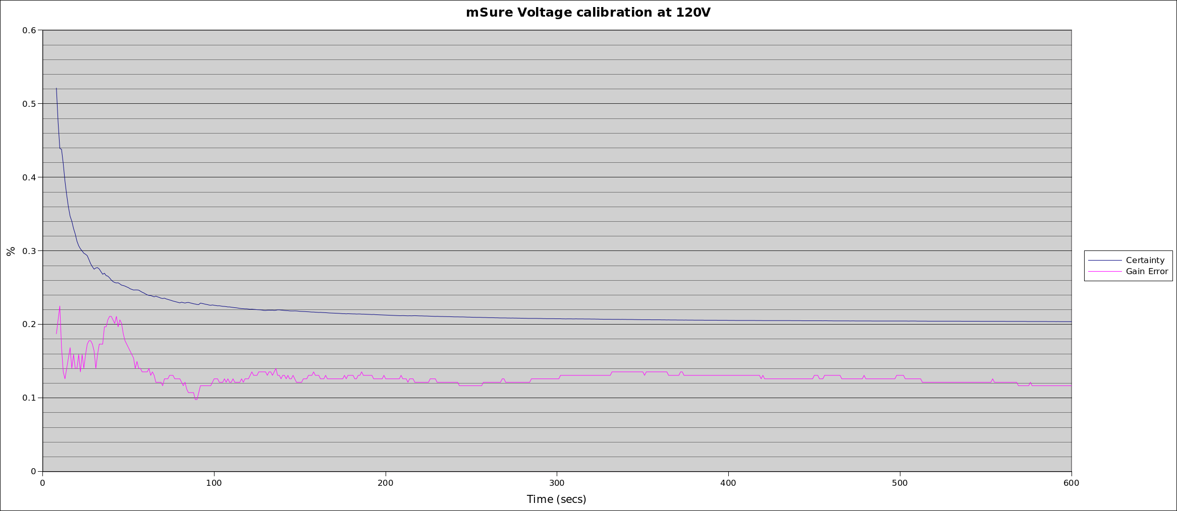
To overcome those challenges, mSure does a lot of sampling for a long time. The results get pretty impressive after about 1 minute. If you haven’t turned it off after 10 minutes, it turns itself off. There are two registers you can poll throughout the run: the currently recommended gain adjustment and the confidence level in that recommendation. It’s up to the meter designer as to how often they run mSure, and whether they run it for a set time, or until a specified confidence level is achieved. For these experiments I let it run for a the full 10 minutes, but it mostly got about as good as it was going to get after 2 minutes.

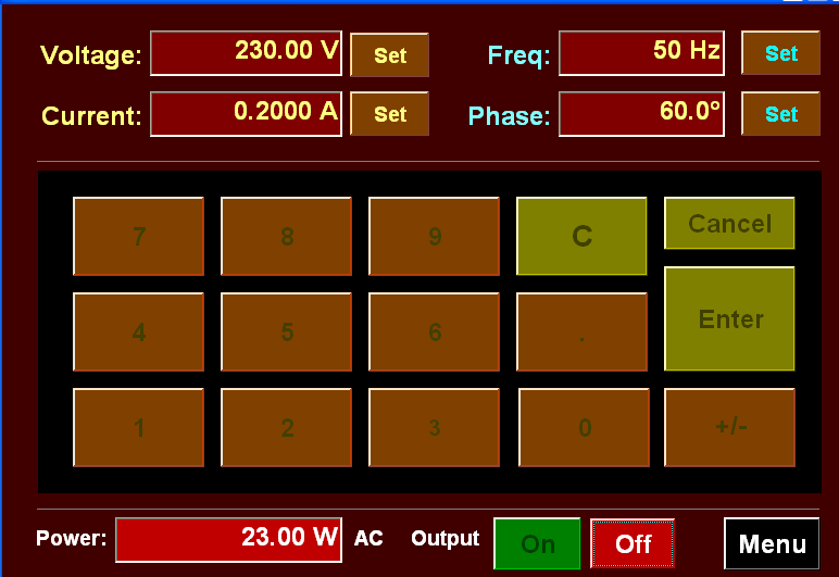
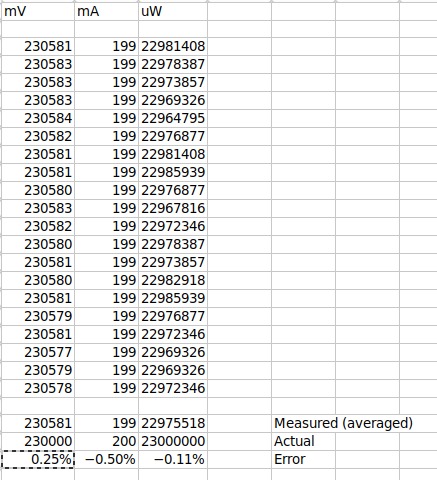
The first step was to set the shield up with a “nominal calibration”, i.e. do all the maths involving the maximum input deflection, the nominal voltage divider and the maximum register counts. I then used that to measure a reference voltage of 230V from the calibrator. Even with just the nominal calibration, the results were impressive: it read the 230V as 230.577V, so was reading about 0.25% high. Then I let mSure run and it recommended a gain adjustment of x0.9982 which brings the reading down to 230.162V, so it had brought the error down from 0.25% to about 0.07%.

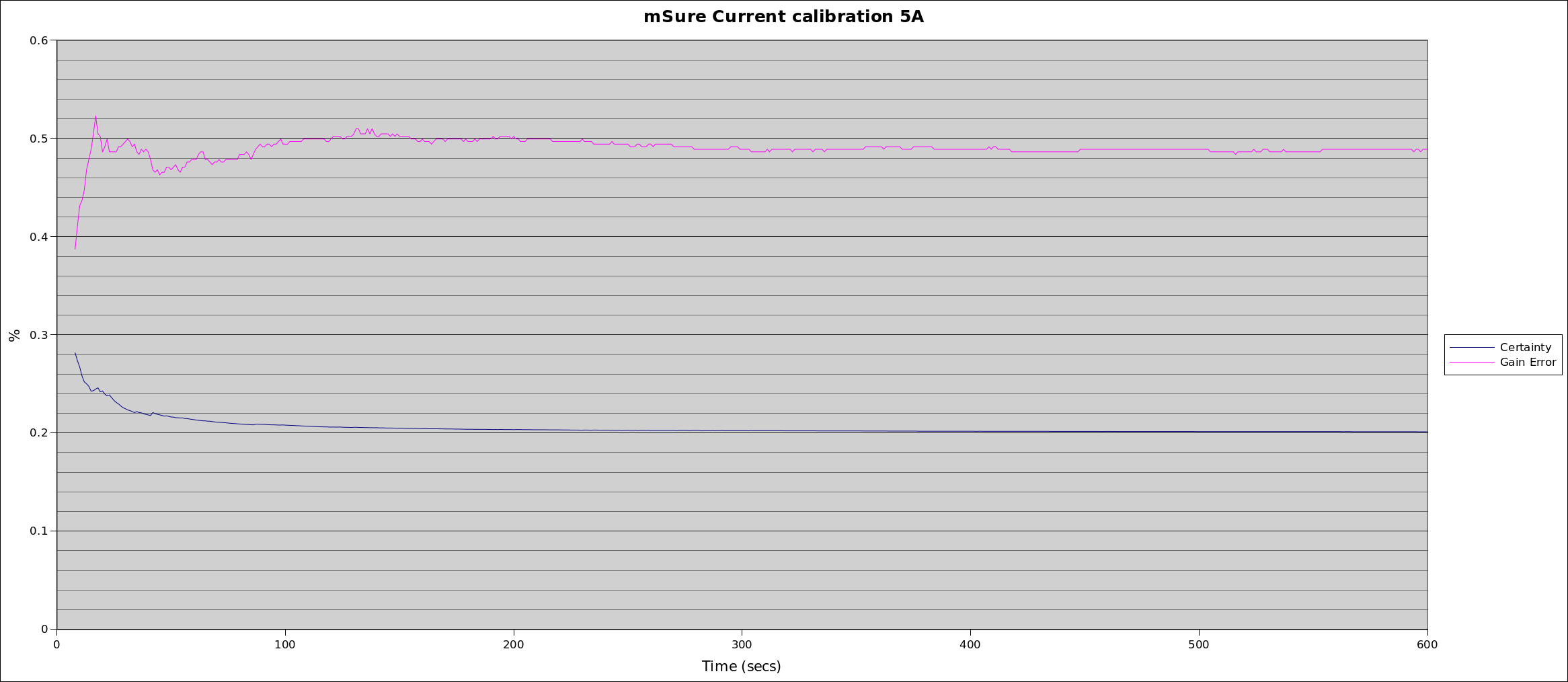
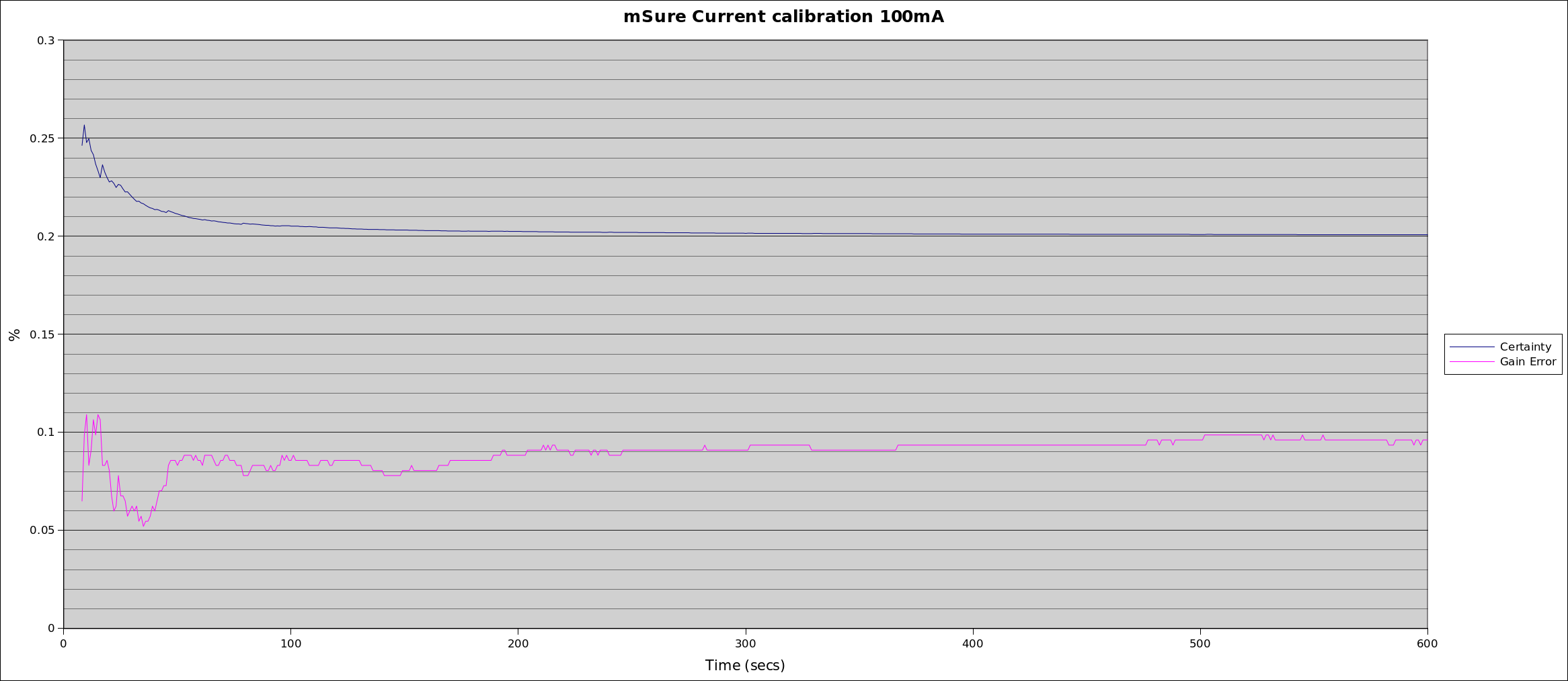
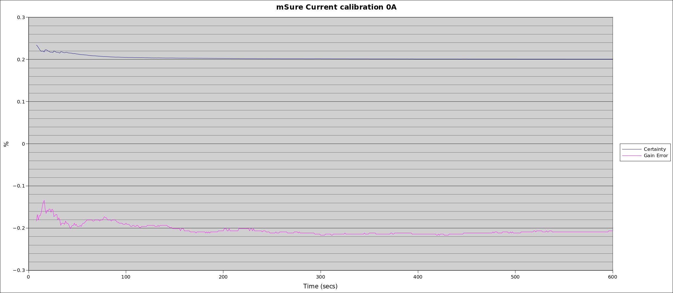
Below are plots of the mSure run at various input voltage swings. They don’t all land at the same place but each of them significantly improve the 0.25% error you get if you just stick with nominal.


I’ll post the I channel findings in a separate reply.

2 Likes

On the current side, the principles are basically the same, except that IAMS is a current source. Its signal is injected into the load side of the shunt and then measured via the normal differential shunt inputs (IAP/IAN). The datasheet gives some clues on how big the current signal is:

but by the time they run that through a 1mR shunt it’s down in the uVs again - and way too small for me to be able to get a scope pic of.

I passed 5A through the shunt and with “nominal calibration” the device read that as 4.985A, so an under-read of 0.32%. Then I did three different mSure runs with different load currents flowing through the shunt and got mixed results. The worst was an over-read of 0.49% (5.024A) and the best was an over-read of 0.09% (5.005A). That bad one is slightly out of spec, so probably warrants further investigation. All my load currents were sinusoidal.


So in summary, you can get extremely good results with 1% resistors, but even if that was down to luck (or you decide not to use 1% Rs), mSure will come to the rescue. There’s no need for any precision reference voltages or loads as they’ve built a calibrator into each IC. It also allows periodic calibration checks in the field to check if the resistors have drifted too far from their original values.

1 Like

Exactly like the thyristor drives that were made by the firm where I did my student apprenticeship, so I know exactly what the dangers are. Plus - it was common practice then, totally illegal now, to not earth the 'scope chassis, so when the 'scope earth was clipped onto the 0 V rail, the entire 'scope was live to line.

As you say, anyone not trained and not used to working on live equipment must stay away. @glyn.hudson and @TrystanLea can confirm this, but I believe it’s the principal reason for OEM not using an energy measurement i.c. in their designs.

Having dealt with that, thank you for a most interesting and enlightening series of posts. I’m in awe of whoever did the signal processing to get those sorts of results out of those waveforms.

Yeh, in order to get those scope pics I used an isolated supply, with a very low current limit in case I did screw up. The scope’s protective earth remained active at all times.

I’m guessing they focus on their edges. They generate them so they know when to look out for them, and while they’re slow, they’re not hugely slow compared to a 60Hz sine wave:

Their edges will always land on a different part of the sinewave too. In some ways, that “random” addition of the AC component might actually provide some useful dithering.

That’s all at least true for V, the external I signal can have edges of its own depending on the nature of the load. But even if their edge does happen to land on a SMPS current-draw edge, it hopefully won’t again for quite a few cycles. And I don’t even know if they use the same signal for calibrating I. I think I’d have to hack the shunt to see that.

Energy ICs don’t have to sit directly on one of the supply rails - in this case I think that’s more a function of them using a shunt. If you stick with CTs for measuring I (especially 333mV CTs that effectively come pre-calibrated from the factory) and a precision divider for V, you can get some pretty spectacular accuracy even without mSure. There are techniques for ensuring there’s plenty of R between the IC and either of the supply rails.

I should have added, in case anyone is thinking of replicating that, that’s in addition to isolation, not instead of isolation.

Of course I understand that, but there’s still the certification problem and the need to ensure that non-technical users can’t hurt themselves through their own ignorance of the dangers. I don’t know what it’s like where you are, but here I get the impression that I’m responsible for everyone’s health and safety except my own!

And I figured I shouldn’t finish off without a real power measurement. Setting aside for a moment all the safety and installation problems with using a shunt, the one big advantage is no magnetics, so there’s little opportunity for introduced phase errors. Still using just the nominal calibration (so not even an mSure run to improve things) I chucked a 200mA 60° shifted I signal at it. CTs often struggle at the low end and start to introduce significant phase errors. It measured the resultant 23W load as 22.976W.


Calibrator settings.

Measured results:
power_spreadsheet_shot
20 secs worth of 1-sec data.
Voltage bounces around by a few mVs
Current is steady down to the mA
Power bounces around by about 20mW.

2 Likes

That should be close enough for most people. :+1:

Thanks, Very helpful! I got calibration problem. i using arduino library, but on nrf52840. voltage calibration is within 0.4%. current is wrong value. uncalibrated meter give near values. my shunt is 220uOh and i set gain to 32 (0x0001C). Target_AICC = 1.9050 Target_AVCC -s 13.4245. my board is custom board followed by reference to kit. Please, advice what to check.
Thanks