and of course monitor our usage and PV system (no battery yet) CTs on the relevant wires is fairly easy to do albeit inside the fusebox itself
and monitor our solar hotwater system (about 5m from the fusebox)
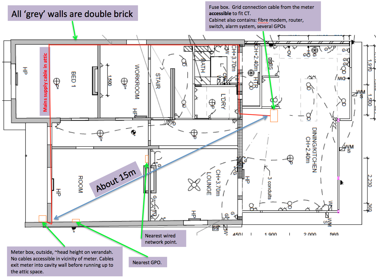
At the moment the main conflict seems to be locating the emonPi near the meter for which I would have to do some imaginative access creation and cabling to get power & signal cables to an emonPi located in the front room and have questionable wifi connectivity to the fusebox & emonTx. I already have a wireless access point at the front of the house because the wifi signal struggles to get there. (I realise the emonPi uses different (lower) frequency comms. compared to 2.4 & 5GHz )
I would welcome suggestions and advice on how best to optimise our installation before placing any orders for parts.
Hi mate, also in skipland (melbourne), I,m using an emontx v2 for solar data and an emontx shield running mk2pvrouter software to heat the hot water. The tank is around 11 metres away and I find that cat5 cable does the job well as the current transformer are current and not voltage,so they adjust to supply the current required. What I,m saying js the current transformer distance should not be an issue. I currently have issues with the wifi dropping out but I believe this is a pi issue regarding the broadcom chips rather than an emon issue. I hope to sort that when I get the dreaded nbn and connet directly to the router. I have found the rf signal to be good using the little wirewound antennas off ebay.
Having completed a fairly major renovation the option to run more cables around is a bit limited - hence the interest in wireless solutions, at least for the hot water monitoring side of things. Putting an emonTx near the tank should be no problem (I must admit that part of the monitoring fantasy was to read the controller (looks at collector temp. and tank temp. and starts/stops the pump based on those data) via its RS232 port.)
The experience you refer to with the “little wirewound antennas off ebay.” - is that in a solid brick house?.
Your remarks also make me wonder if I’ve understood the basic architecture we need, mentioning as you do “using an emontx v2 for solar data” and “an emontx shield running mk2pvrouter software” and no mention of an emonPi. . . more reading for me I suspect.
It doesn’t seem too convenient to use the optical sensor on the meter so if it was me I’d skip that and mount your equipment at the switchboard. Use a CT on the mains active cable entering the switch board and a CT on your solar active cable. You would also have to use the 9vac plug pack to measure the AC voltage and to determine if you are exporting or importing power on the mains.
It should be possible to use an emonTH to send the optical pulse input to your emonBase (= emonPi?), but if you have PV, as @rob1 says it’s questionable what information you gain, because of course the pulses stop when you are exporting. All you’d get is confirmation/calibration of imported energy.
Hi Tim, my setup with the pvrouter (diverts excess solar into a 1.8kw element of a twin element tank), has a temp sensor inside (Dallas ds18) its insulation to send the temp to an emonbase, being scottish background the pi was a bit expensive for me😁. Not sure how you could use rs232 with these gizmos. You could use the pi with 2 ct,s using the cat 5 cable as an extension lead for the ct,s and have the pi near where you need it for a good rf signal. I have not tried the pulse count on the emonbase as I,m using it with a watts clever display to help calibrate my system. For display of my solar data I wanted something like the emonglcd, so I built a display with an arduino running a 5" touchscreen (Nextion). An emontx collects the solar data. With emoncms you can put it all together for display on your phone/pc etc. Hope this is helpful, regards Martin.
Many thanks to you all - lots learned already! Mainly that the LED pulse doesn’t measure the exported power and so does indeed seriously reduce the value of it if you have a PV system.
So I seem to be converging on a much more straightforward emonPi near the switchboard along with an AC plug pack to sort out the electricity consumption, generation and use an emon TX to grab a couple of temperatures from the HW system.
A display in the kitchen/living room for ‘The Boss’ is also of great interest so Martin’s screen project also sounds very useful.
Hi Tim, that would be the way to go, as I said you can use cat5 twisted pair cable (plain old network cable 4 pairs in it) to extend the CT cables and/or the Temp sensor. Use a small stereo plug and socket to extend them so you can put the Pi where you want. The AC plugpack can plug in near the Pi.
If you have a really long cable run or interference problems, there’s a piece in ‘Learn’ about using microphone cable. But if your run isn’t significantly more than 15 m, you should be ok with Cat n (it’s not critical - you’re interested in the twisted pairs, not speed!). If you’ve got a screen, earth it if possible, especially if your cable runs in amongst mains cables.
Once again, my thanks to Martin, Rob W and Rob 1 for taking the trouble to guide me towards what I think I need.
I think I’m going to set about this in a couple of phases (abandoning the optical meter sensor and the wiring or WiFi probs it may have) and loading the ‘cart’ as follows:
EmonPi PV bundle
EmonTx
EmonTx Arduino shield SMD + 3 DS18B20 temp sensors (SHW tank water temp at outlet, tank water temp near return from collector, water temp from collector (this may exceed sensors range. . . ))
EmonPi solar bundle sorts out all the basic electrical energy monitoring. Includes
a base unit
2 CTs (grid supplied and generated power)
AC voltage sensor
Emon TX + Arduino shield to monitor a SHW storage tank temperatures (3 measuring points)
The hot water tank is 5m away (not shown but outside (again typical in Oz) at the very top right corner of the plan in the 1st post) from the switchboard where I’d locate the EmonPi and not at all convenient to connect by cabling - hence the (somewhat extravagant) use of the TX and under use of its main power monitoring capabilities. FYI We have neither pool pump nor AirCon as big consumers (and that is NOT very Australian!!)
Hi Tim, you mention a Shield, the EmonTx is basicaly like a Arduino Uno with a shield, so you do not also need a shield if you buy the EmonTx. If you do want a EmonTx and a shield you will also need a Arduino Uno to take the shield. This would be 7 CT inputs so maybe to many I,m thinking. Hope this makes sense.
My understanding was that I need the shield to read the temp sensors. . . . With your questioning this, have I misunderstood . . . ? can the CT inputs also be used to read the temp sensors?
That’s why I asked - yes, the emonTx and emonPi can read by default 6 temperature sensors, more if you edit the sketch (and emonHub to receive the extra data).
The EmonTx is to all intents equivalent to an Arduino Uno plus emonTx Shield.
But if you don’t need an emonTx for the 4 current measurements, and it’s possible to wire the temperature sensors (only one 3-core “telephone”-type cable) back to the emonPi, then you need neither emonTx nor Shield+Arduino.
If you can’t wire back to the Pi, then if it’s only temperatures you want and feel up to the challenge, you might like to look at an Arduino + RFM69CW Shield (I think they exist), or a bit of breadboard and the RFM69CW module, plus 1 resistor to terminate the One-wire bus. However, by the time you’ve boxed it and added your time and effort etc, the price difference might not be significant.
Have you considered instead of relying on wifi, you could buy a couple of “Powerline” network adaptors? These run data over your electrical cable plant and effectively put a RJ545 Ethernet connection anywhere you have a GPO. They are pretty cheap these days. $50-$100 for a pair?
A friend who lived on a farm in rural Scotland had a bad experience with those and his neighbour’s milking machine - they blew up on the big induction motor’s switching spike.
Wiring back to the Pi is surely the best but running wiring around the ceiling of the new kitchen is not going to earn me much credit with the Boss. . .
The powerline adaptors are an interesting idea - I might have a look. Robert’s Scottish friend’s experience is troubling but in a rural area, on a farm (at the end of a distribution arm?), with a largeish reactive load cutting in and out is not quite what I have here in suburban Melbourne - so perhaps the risk is worth exploring.
But I’d still have to find devices to read temperature and transmit the data to the Pi - wouldn’t I?
I reckon I’m pretty handy with a soldering iron but electronics design/experimentation of the sort Rob mentions would - without help being close at hand - probably be stretching my abilities. . .
For my abilities I think the TX is probably the way to go.
If you’re going wired Ethernet to a powerline adapter, Arduino + 5 V (or whatever) power and taking the temperature sensors straight in to that is an alternative to the emonTx (433 MHz) or emonTx and ESP8266 (for Wi-fi).
Or for the tank temperature, you could use an emonTH with external sensors (it will accept 4 by default on screw terminals, in addition to the internal temperature/humidity sensor). It only sends data infrequently - a little faster than once per minute - so on battery power you should get a reasonable battery life - or you could add a 5 V power supply via the screw terminals, as mains is probably available.
Thanks Rob. The emonTH is now obviously the solution!
I’d only glanced it earlier and figured it was not suitable for my purposes but now I read it can be configured (different firmware) to read multiple temp sensors, it is the way to go. (It will also give me the opportunity to test the wifi range from the meter to see if the pulse counter might work). And yes I have a GPO at the SHW tank so could power the TH like that - additional sensors have a higher current draw but starting with batteries should be fine.