I’m trying to build a simple power monitor based on Arduino Nano v3 (cheap chinese clone) and a custom circuit with 230 to 9V transformer on the voltage side and Talema AC1025 CT on the current side.
The difficulty is that when I power up my system from USB port of my PC it’s working almost OK. Almost means that without any load the current is not equal to zero (0.01 to 0.05A). So I decided to power up the system with a 12V 2A power supply. I connected VIN and GND inputs of my Nano to the supply and 5V and second GND pins to the measuring circuit. Now Arduino board is still working great. BUT! The current is ALWAYS equal to zero! Regardless to the load. And the voltage is fine (217.0 to 223.5V as usual in my city ).
I measured the output voltage on the current circuit when powered from USB andthe load is present, the voltage floats proportionally above the 2.5V according to load power (and the current). When the system is powered autonomously it always stays at 2.5V. Without any changes.
About my current transformer. It’s a Talema AC1025, the 25A max transformer. According to manufacturer’s recommendations the burden resistor is 100 ohms.
First, the non-zero current (10 - 50 mA) is probably noise being picked up from somewhere, most likely from the digital part of the processor or via the power supply.
Second, is the 5 V supply out to the analogue front end present when you are powering your Nano from 12 V? If not, there’s your answer.
Third, if the d.c. average voltage at the two analogue inputs A0 and A1 changes according to the current you’re measuring and mains voltage, then something is wrong. Those two points should stay at 2.5 V d.c always, but with up to about 1 V rms of a.c. superimposed on the quiescent d.c. voltage. See the diagrams in Resources > Building Blocks > CT sensors - Interfacing with an Arduino and Resources > Building Blocks > Measuring AC Voltage with an AC to AC power adapter
Note that with your 100 Ω burden, you can only measure to about 16 A before you overload the Arduino input. Decrease the value of your burden resistor if you want to measure up to 25 A. (You overload a current transformer when you increase the value of the burden resistor.)
When I power my Nano with 12V DC the voltage on the 5V pin is 5.00V.
Today I connected my Nano board through the DC-DC converter with output of 5.00V. The measuring circuits are powered from the same source. And still no luck: current measures are always zero and working great (almost) when powered with USB.
Voltage on A0 (pin that is connected to CT part) is 2.48V. When powered with USB the A0 pin has 2.34V (but 5V pin is also not actually 5V, it’s 4.70V).
Speaking about my CT: as I said it’s not a SCT that is “standard” to use with EmonTx. It’s an AC1025 from Talema. Here is the datasheet: http://www.kosmodrom.com.ua/pdf/AC1025.pdf. Following this doc I used 100ohm burden resistor. I didn’t find any info about the turns number in AC1025 but it said that the turns ratio is 1:1000.
So I still cannot understand what happens when I connect the current measure part to the external 5V. Like there are different volts in USB and DC power supply …
The maths for the CT is simple: The ratio is 1000:1, or more properly 25 A : 25 mA (CT ratios should always be given as currents - a 1000:1 CT would measure 1 kA with a secondary current of 1 A). Yours is rated to 25 A, so it will have a 25 mA max secondary current, and you need a maximum of 1.6 V rms (a little less than 5 V peak-peak) across the burden resistor. The 100 Ω that the data sheet states is the maximum value for satisfactory operation, not the value you need for a 5 V Arduino. You will actually get better performance (lower errors) with a lower value burden.
There is something very silly happening.
The voltage input and the current input work in exactly the same way. Therefore both should behave similarly.
What is the actual voltage of the 12 V supply when it is powering everything?
Do both A0 and A1 measure ~2.5 V at the input pin in both cases - USB 5 V supply and the 12 V supply?
Are all the GND points connected together?
Does the voltage input work with both USB 5 V supply and the 12 V supply?
It’s 12V. As I said before now I have connected a LM2596-based DC-DC converter to lower the voltage to 5.00V and now my Arduino is powered with 5V via the 5V pin and GND. The measuring circuits are connected to the same converter.
On external supply:
A0 (current) is 2.49V,
A1 (voltage) is 2.43V.
On USB power:
A0 is 2.34V,
A1 is 2.28V.
And I’m (almost) sure that internal Arduino voltage is not 5V when it is fed by USB.
Yes, all the GND pins are connected to one node on the DC-DC converter.
And yes, there is something very silly happening. But what exactly?..
That should be OK. emonLib should be able to handle those differences.
I don’t see how it can be a fault in your analogue front end. Are you able to try any of the other analogue inputs?
About Ethernet hardware part: it is fed by the same 12V supply (it can supply current up to 2A i.e. up to 24W of power so it must be enough for both measuring circuit and Ethernet controller) through the separate LM2596 DC-DC converter set to 3.3V DC. The ground nodes of main scheme and Ethernet controller are separated.
Just tried A6 for the current and A7 for the voltage. But nothing changes.
What do you mean by this? That does not seem right to me. How are the two related? Or is there an opto-coupler between the Arduino and the Ethernet parts?
The problem is that ENC28J60 consumes (relatively) lot of power (something around 500mA) and 3.3V of voltage. So it cannot be connected to Nano 3V3 output. I use external supply (12V → 3.30V) to power it. And there are no common power connections between Nano and Ethernet shield, only digital pins to interface with last one.
Could it be the source of the problem? Is it worth to join all the grounds (3.3 and 5V) together? Or my username is «not compatible» with this project?
But the digital pins need a reference - there is no such thing as absolute voltage, it is only by convention that we regard the general mass of the earth as 0 V, or GND (more properly COMMON or 0 V) as our reference when measuring voltages on a particular circuit board. Unless you tie all the GND/COMMON points together, there’s nothing to say what the signal voltages are, for example +5 V on one could be [think of a number] -87 V with respect to the common rail on the other.
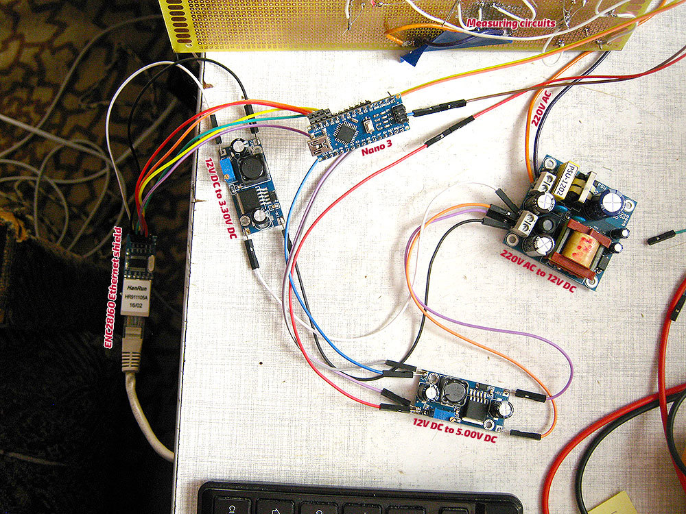
I cannot read the pin designations on that photo, so it does not help.
Recently checked the connections with the multimeter and found that all the ground nodes in scheme are tied together so the problem is not there I think. Could it be the Nano inner problem with analog reference voltage? I.e. on USB it works fine because the AREF value is set in other way than in «autonomous mode». But if so why the voltage detection is working perfectly?
There is one more problem (with Ethernet module stability) but for now I need to solve the first (and the main) one…
I can’t help thinking that there’s something very silly that you and/or I have overlooked. Is there something special about AI0 which means it gets “stolen” when you are using the 12 V power supply? Can you try another input - say AI2 - for the current? (Don’t choose 6 or 7 - I’ve read they could be special.)
Forget emonLib etc, and go back to basics. Try writing a very simple sketch to read the raw values from AI0, AI1, AI2 (try them all!) , and print to serial output every second or two. (I assume you have a programmer and can monitor that directly, not going via Ethernet etc.) You should see around 512 from each with the input bias circuit connected but with no voltage and current inputs connected, and apparently random values when you connect the transformers. Or you could “pull” the midpoint with a low value (say 1 kΩ) pot connected across the 5 V supply, wiper to the analogue input, and check that the inputs read 0 (0 V) to 1023 (5 V) or thereabouts.
That’s about the bottom line! Anyway, we got there in the end, and it’s good to know that everything is now OK.
[N.B. It wouldn’t be the first time I’ve been caught by something like that. My favourite is to edit one sketch and load a different version of the same name, and wonder why what I’ve changed has no effect. ]
Oh, one more question, please: what about my CTs? I used 100 ohm burden resistor according to the datasheet and there is a diagram thet shows that the voltage on full load (25A) with 100 ohm burden will be 2.5V.
I am trying to build a nano sketch to send data to a local server emoncms, with ethercard library. Can you publish the complete sketch please? in your sketch I can’t see the json string. Thanks.
 ).
).
 …
… Or my username is «not compatible» with this project?