I wired up this circuit and it used to work but after not using the circuit for a few days when I turned it on again it’s not working anymore. It over-reports a value of ~30 watts and fluctuates a lot more now. Previously, when the CT was either not clipped onto a wire or it was clipped to a wire with no current, arduino showed a value of exactly 0, now it does not. How can I fix this? Is my CT broken?
Things I’ve done differently than in the tutorial:
Instead of a 33 ohm resistor I’m using two 68 ohm resistors in parallel for the burden resistor.
Because of this, I’ve changed the calibration value to 57.97 from 111.1 in the code (although I’ve tried using the default 111.1 too, that doesn’t fix the problem).
What I’ve tried to fix the problem
rewiring
changing the wires entirely
changing the audio jack
moving wires far away from each other
checking if my arduino’s analog input is broken by connecting it to ground and 5v and checking if it reports a value of 0 and 1023 respectively. (it does)
connecting the arduino to different power supplies
I doubt this very much - but you can check for continuity: you should measure about 110 Ω between tip and sleeve of the plug.
This suggests to me you’re using a YHDC SCT-013-000 current transformer. Is this correct?
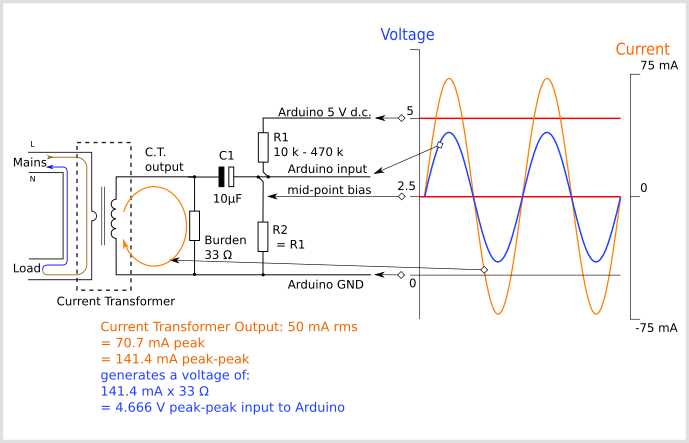
I don’t understand why you did this - the value of the burden is almost the same whether you have one 33 Ω resistor or two 68 Ω in parallel (= 34 Ω). The calibration constant is the current you need to give 1.0 V a.c. across your burden resistor.
You don’t say how you’ve constructed the circuit, or what you are using for the power supply. The usual cause of a large reading when there’s no current flowing is electrical noise - either coming in from the public supply or originating in your 5 V d.c. supply, or a combination of both. (Note: doubling the sensitivity doubles this too.)
When you think about it, 100 A at 220 V represents 22 kW, and a rms voltage across your burden of about 1.6 V. 30 W is 733 times smaller, so about 2.2 mV of unwanted signal finding its way into the analogue input will read as 30 W.
I believe what you wrote - but in all honesty I’ve never read exactly zero, even with the custom printed circuit of the emonTx, I generally see about 3-5 W of real power, when no current flows. 30 W does seem excessive.
Have you tried feeding your Arduino from the 7 - 12 V input for an unregulated d.c. power supply, and taking 5 V for the c.t. bias from the Arduino’s regulator? I’m not an Arduino expert, but some users have reported a good improvement by doing this.
You could also try rearranging the input components to follow the configuration we use in the emonTx4
(Hardware — OpenEnergyMonitor 0.0.1 documentation) - where one side of the transformer (voltage including the voltage divider or current with its burden) is grounded and the other side couples via the capacitor to the bias resistors and the analogue input of, in your case, the Arduino. This might show an improvement.
If you only need to read up to 50 A, or up to 33 A, then you can pass the main cable twice and three times through the c.t, (and change to calibration to 111.1/2 or 111.1/3 as appropriate). This should reduce the unwanted reading by the same proportion.
you should measure about 110 Ω between tip and sleeve of the plug.
It shows 190 ohms (the same value when everything was working).
This suggests to me you’re using a YHDC SCT-013-000 current transformer. Is this correct?
Yes, and I changed the value because I read it here. I used a breadboard to construct the circuit, the circuit connects to arduino’s 5v and ground pins as shown in the diagram on that page, the arduino is powered via a usb cable connected to my computer.
I believe what you wrote - but in all honesty I’ve never read exactly zero
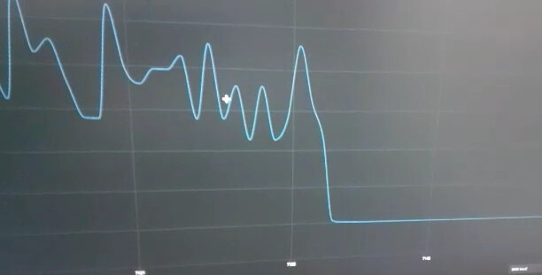
Maybe I’m misremembering the exact value part, but I do have a picture of what the graph used to look like when I cut power: .
Now it’s just a mess.
Have you tried feeding your Arduino from the 7 - 12 V input for an unregulated d.c. power supply,
That’s the barrel jack connector right? If so, no, I do not have that connector.
You could also try rearranging the input components to follow the configuration we use in the emonTx4
Sorry, this went right over my head, is there a simpler diagram I could follow?
you can pass the main cable twice and three times through the c.t
Oh, I’ll try this one out!
Although, what I’m curious about is why did it work before and suddenly it doesn’t!?
OK, I’d briefly forgotten it needed changing for the 5 V Arduino.
I’m afraid not. It’s something I ought to write up to go into the ‘Learn’ section. I’ll try to find time to alter the existing diagrams in Learn.
I think something else happened at the same time, which you didn’t notice, that caused it to go down to exactly zero. Elaborating what I wrote above, to read exactly zero, the input must remain within one step of the ADC’s transfer curve - that’s 1/1024th of the input range (i.e. ~ 5 mV) wide. Even if the bias voltage means the average voltage sits exactly in the middle of the band, it doesn’t need much to go outside and into the next band, and the ADC output will flip from (say) 512 to 513 on a positive-going voltage and to 511 on a negative-going one. If the average is right on the edge of a step, then almost nothing will flip the output to the next number.
One more thing I noticed right now is that I get the same value (~30 watts) when the CT sensor is disconnected and when it’s connected but not clipped onto a wire or clipped onto a wire with no current.
This is what I’d expect if noise/interference is getting in via the power supply or the a.c. adapter.
What do you read with both the a.c. adapter and the c.t. unplugged?
That more than likely explains the high value. You referenced the build instructions for both current and voltage - so how was I to know you were only using the current input?
When you are using the voltage input you are multiplying each pair of current and voltage samples to get power and then averaging, when you are not doing this, the rms calculation ‘squares’ each sample value, removing the sign of course in the process, averages the samples squared and then takes the square root to give the rms average current, then you multiply by the voltage to get apparent power (volts × amps). But having squared each sample, the noise/interference cannot be averaged out and instead it’s always added, so it shows as a large value.
A “clean” d.c. power supply - if this is indeed the problem - should help. If you have a 9 V regulated or unregulated adapter, then this too is worth trying - via the 9 V input.
Here’s a circuit diagram showing how you would connect the c.t. in the way it’s done in the emonTx4. In your case, this might or might not help, because I think this might be only a part of the problem.
 .
.