Arduino current monitor - Calibration?

Hi,
So I am planning on building a arduino energy monitor. For now
I am following this guide (Have all the same components, except I am using a Arduino Mega). I am getting readings, even if the device is turned off (60w light bulb). When I disconnect the CT I also get the same reading… Is this normal? How do I eliminate this?

Current is around 0.2 and Watts around 45 with no load?

That is a common problem, and it is in the FAQ. It is worst when (a) when you are using a breadboard layout and (b) when you are measuring current only.

What you are seeing is electrical noise, possibly from your power supply, possibly picked up from appliances nearby or conducted on the mains wiring, and possibly generated by the digital side of the Arduino itself.

It is worse when you measure current on its own because any noise that is picked up is rectified by the rms calculation, whereas when you add voltage and calculate power, the noise tends to average itself out and largely disappears.

There’s not much you can do about it. A good quality power supply might help, as will careful attention to wiring (i.e. keep the wires between the burden resistor and Arduino as short as possible, twist them so you don’t have a loop with a large area), and maybe add extra smoothing to the 5 V or 3.3 V power rail.

Also you don’t say which c.t. you are using, but if it’s our recommended SCT-0113-000, 60 W is around 260 mA, that’s 0.26% of the maximum reading. If you need to measure currents that small, then using (say) 10 times through the c.t. for the primary winding and changing the calibration down by a factor of 10 to suit should reduce the effect of the noise by the same factor.

1 Like

Thanks,
I am still looking a suitable AC/AC adapter for the voltage sensing in my area. So only current for now. This is all still on a breadboard, the circuit is powered from the Arduino’s 5v (Arduino is powered from my PC though). Must I power the arduino from a AC adapter, will the help? I am using a 100A SCT-0113-000 with a 2 x 47ohm res in parallel, + 2x4.7ohm resistors in series (Had no 33ohm for testing, but will be purchasing them with all the other components I need once testing is done), - this is planned for the main circuit (Total apartment usage). I will most likely use 50A/1V CT’s for all the different circuits (Water heater / stove / plugs / lights)

It might do. If you search this forum, I know people have measured the effect the various ways that you can power an Arduino has, but for which Arduino, whether that will apply to yours, I don’t know.
See https://openenergymonitor.org/forum-archive/node/10111.html

Note you can increase the sensitivity of measurement a second way, by increasing the value of the burden resistor, but this comes at the cost of increased distortion and phase errors. A c.t (any c.t.) performs best when working into a short circuit, but then of course there is no burden resistor and no voltage to measure (and so it won’t work!), so the choice of burden value is a compromise. We generally advise the value of resistance which will allow you to get the maximum input voltage (in your case ~ 1.6 V rms) at the ADC input at the maximum current you want to measure.

If memory serves, there’s a post on the old forum where the user mentioned a considerable
improvement when the Arduino power source was changed from their PC to a DC power supply.
(but not the same post as linked to above)

From a post by MartinR:
https://openenergymonitor.org/forum-archive/node/2446.html

How are you powering your board? If it’s via USB from a PC then you will have lots of noise on the 5V line

and one by Roger Clark: (STM32Duino forum admin)
https://openenergymonitor.org/forum-archive/node/11021.html

I’m also seeing a lot of supply noise coming in from the PC via USB, which I don’t get at all when I run the board from a separate USB PSU.

A clean power supply is actually very hard to achieve, even without the noise from running it off of the PC’s 5V supply for USB. Using USB power from a PC is fine for many things, but it will be noisy. Even with a clean supply, using an esp8266 will make it really unsuitable for anything that needs a stable-low-noise supply. While I suspect the esp8266 is especially bad, all MCUs generate a fair amount of noise.

Having said that, it depends on what you need/want/can afford. Even a system with some amount of noise and inaccuracy can provide valuable information with which to make decisions. My Brueltech ECM1240 used to say that my dryer was drawing 7W all the time. I wasn’t sure if I should believe it. But, the dryer was one of the first digital ones and has a power supply that is always on. I was going to put a hard switch on it, and even bought one, but never got around to installing it. Now I have the dryer on an Iotawatt and it says it is drawing nothing (when off). Which one is right? I am not really sure. But I have done other tests that lead me to believe the Iotawatt is. I have one CT on a circuit where I can control exactly what is on. It shows 0W when nothing is on and the correct value for known loads (small and larger)
Here is the loads from an answering machine and computer in standby

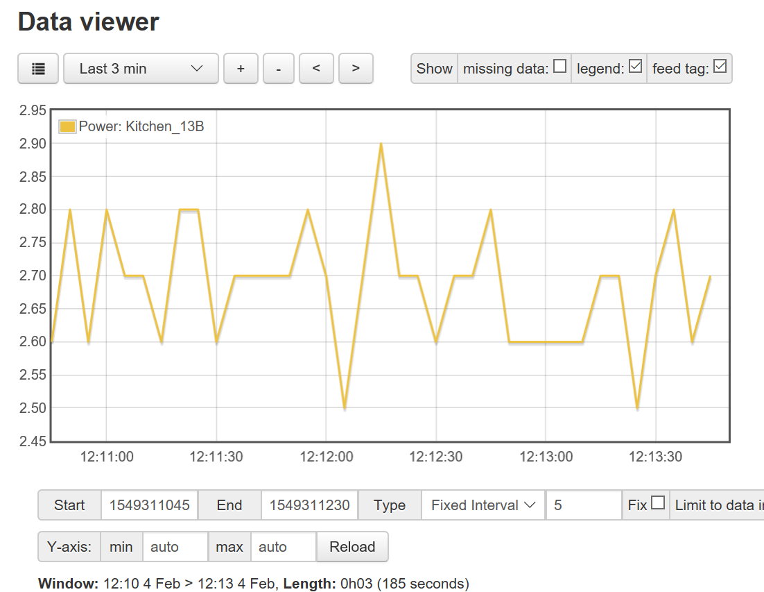
Here is the power that my range draws for the clock:

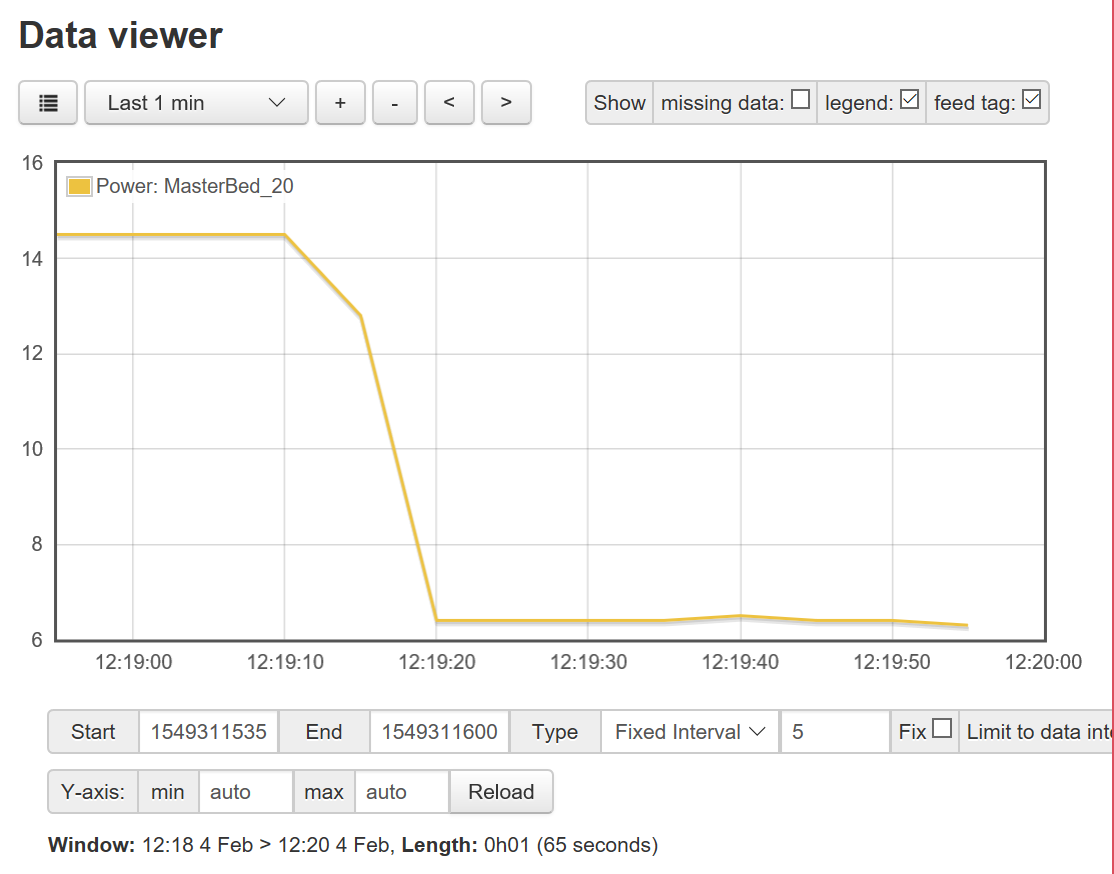
Here is the bedroom with only the closet light and smoke detectors and other always on load and the transition when I turned the light out:

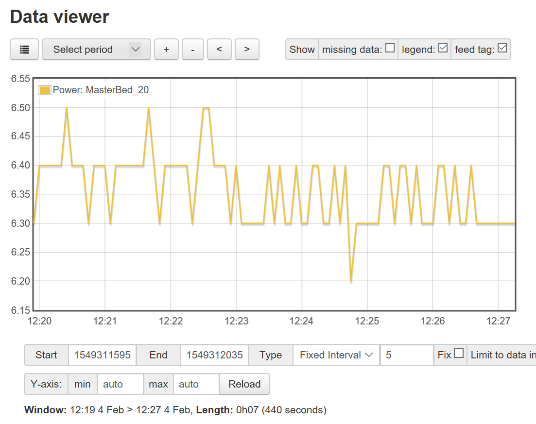
and here it is with just 6 Nest smoke detectors, the control for a sleep number bed, and Big Ben Moon Beam clock. Since it has a 50A CT on the circuit, the load is at 0.1% of full scale. With a consistent load the results are very consistent.

Here is the 7 min view:

Here is the basement shop:


Looks like Alexa woke up and checked for updates

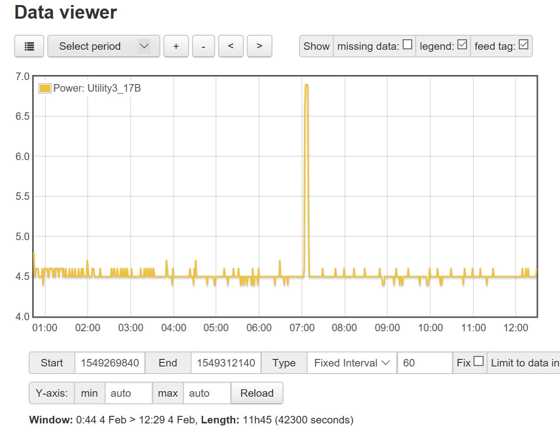
Now here is my utility room with the new circuit I added:

The first jump was when I moved some additional esp8266 based stuff over to the new circuit. The second was when I moved my PC that is running all my home automation stuff (NodeRed, MQTT, InfluxDB, Grafana). It stays on always, but turns off the display after 2min to save energy. You can see the signal got a lot more noisy when I added it. That is because it is always changing how much power it is using based on what it is doing, but is still averaging at about 5W, which is little more than RPi, but way more capable performance wise.

Anyway, my point is that it is certainly possible to get reasonably accurate results at low power levels, but it is not easy.

Thanks for all the info, really learning a lot and that is the point of DIY isn’t it…
I powered the arduino from a 9v DC Adapter, but was still using the PC usb for serial debug data. I noticed that the noise was around 0.15 and a lot more stable than before (Use to fluctuate from 0.19 to around 0.23). I will attach a 16 char LCD and see if the noise improves if it isn’t connected to the PC USB.

Now for another question, knowing there is noise how do I calibrate this? I am using a 2000 watt kettle, my kill a watt meter shows it running just under 1900 watts. Do I now calibrate it to read 1900 + the average noise? So lets say 1940, or 1900?

What is the quoted accuracy of the kill a watt?
[EDIT] this product page for the P4400 indicates 0.2% accuracy… which at 1900 W is +/- 3.8W
If you believe that accuracy claim, then calibrate it against the Kill a Watt output.

You can also wrap multiple turns of wire through the CT to move your load further into the right zone for the CT.

Hi, do not see the accuracy percentage on the info page for the meter. I will try and wrap the wire around and see if it improves anything…

Lets assume the meter is fairly accurate, still do I use the 1900 wats to calibrate (so my oiutput must read close to 1900 watts (or do I calibrate it to read close to 1940 watts as the noise is around 40 watts)?

I’ve re-read the posts, but I’m still not clear on how you determined the noise - is that with no load connected to the CT?

If so, ignore it completely.

Correct, I have ± 40 watts showing with no load . So I will calibrate the output to show as close to the meter as possible., ignoring the 40 watts.

It looks like you live in a 230V country, you’ve got no VT and you’re reading 0.2A of noise current when nothing is connected. Is that a fair summary?

In that case, the ~40W you’re seeing is apparent power (230 x 0.2). Most of that noise is probably fairly high frequency, much higher than 50Hz. When you include your VT you’ll be multiplying that noisy current signal by something relatively close to a 50Hz sinewave. When you do that, all the high frequency noise in the current will effectively be filtered out of the result, or as Robert describes it above, it’ll average out to zero in the sum of the product (as much of it will be above 0 as below 0).

The result will be your Real Power measurement will be much lower than 40W (hopefully closer to 0W than 40W). If your plan is to add a VT, I’d be inclined to hold off calibrating until you find one.

1 Like

We indeed have 230v when our beloved Eskom can supply it :slight_smile:
The only AC adapter I could find so far is this - out of stock though…

Even if my usage turns out lower than the meter it will be fine (The meter has to be 90% accurate?). I just want an idea of current usage, and then if I change something see if it has any impact on the usage…

So the plan is to build a hat that has all the necessary connectors and circuitry to measure 5 circuits + VT, but only use the 5 current transformers until I can find the ac transformer.

That a.c. adapter looks OK to use, but I can’t say that the calibration figures for our shop one will apply, though they should be a good starting point.

As dBC says, I wouldn’t bother too much about calibration at this stage if you’re aiming to add the voltage measurement, because the “power” you read now is only a best guess based on the voltage being exactly 230 V - so there’s a much bigger variation in 2 kW from the voltage not being what you think, than the supposed 40 W of noise you’re seeing.

1 Like

Thanks,
Will leave the calibration until I get the hat built (Hopefully by then I have a AC/AC transformer).

Just a note here, I found the main problem with the ‘noise’. I didn’t have a female audio jack when prototyping, and didn’t want to cut the CT sensors plug. So I used a couple of crocodile clamps, turns out these 2 wires were picking up the noise (working like antennas). After receiving all my components, I tested it again with a audio plug and now the noise is only around 5W - hopefully I can get this reduces once I solder everything.

I am surprised your PC draws only 5 watts! What PC do you have and what model power supply does your PC use if you dont mind me asking?

I think most of my PCs draw around 50 watts.