I think the flow switch was an option as a failsafe, but now that you have to fit a flow sensor (has to be present on FTC6), then the flow switch is a bit superflous.
Re on-off control. Apart from the normal IN1 room thermostat option, there is the Smart Grid option on the FTC6. Not sure if that is a useful for controlling it.
Thanks John. Any info on how this Smart Grid option works? I could not find much info in the manual about it.
Also, I have a few more questions. The way my plumbing is done I have 3 zones. The closest to what FTC supports is “2 way temp control” I am planning to use the following connections on the FTC6, see in brackets. Correct me if they are wrong.
- Zone 1- Convectors pump OUT2 with thermistor (THW6 + THW7)
- Zone 2- 1st-floor UFH with mixing valve (OUT5) + circ pump (OUT3) + thermistor (THW8+THW9)
- Zone 3 ( not supported by FTC6) - 2nd-floor UFH with mixing valve (I plan to use 3rd party PID temp regulator to control the mixing valve since FTC6 does not support another zone, sounds like a good idea???) + circ pump (either 3rd party control from my smart home assistant to shut off the pump if floor 2 is not calling for heat/cool OR I can connect it in parral with 1st floor pun to OUT3)
I have DHW Tank OR Mixing tank for space heating controlled by 2/3 way ON/OFF spring return valve (OUT4)
I plan to use my smart home to close IN1 and IN6 when all thermostats do not require heating/cooling.
Q1. Since the FTC unit is very close to the DHW tank and Mixing tank, I plan to use its internal pump, so I see no use of the OUT1. When do people use OUT1?
Q2. What is the purpose of OUT14 ?
Q3. I assume I can connect OUT11 ,12,15,16 to my smart home esp32 board to read the operation of the unit and when those components are on/off and use that as statistical info?
Q4. Any idea how OUTA1 0-10v analog output can be used?
Appreciate all your help guys.
Probably a lot easier to use a Heatmiser UH4 and wire the FTC6 as one zone using IN1.
Deyan, I have only used simple setups with Ecodan, basically doing what Nick suggests, BUT be careful with thermostats. Many of the ‘cleverer’ ones are really not what a HP wants. You don’t want a chrono type that pulses. These can be ideal for boilers since they reduce overshooting of temperature. There are a few that have a ‘differential’ to set (e.g. 1/2 degree from cut-in to cut-out. You really want thermostats that talk to each other and ‘collaborate’ so that they spend a bit more time operating all together. This gives a better load for the ASHP. I’m not aware of anything that does this.
Sorry, not found time to answer your questions yet!
It would have to be some sort of script taking the data or HomeAssistant type system.
I dont know about HoweAssistant. I made a system using emontx/emonTH. it had different levels of ‘importance’, and changed the threshold very slightly once the system started. The idea was to ‘encourage’ rooms to heat together. Mine was a bit crude and simple. It needs properly developing by someone.
I’m essentially doing this with my Home Assistant setup with Heatmiser Neo and Tado. Quite straightforward to control. If I could better control my Ecodan’s through HA I’d be off to the races.
Maybe @mjr’s melcloud-mqtt.py project could help you with that.
Thanks @Timbones soon as I get some time I will take a look into this. I’m quite proficient with HA and scripting but not really managed to get a python dev/test environment up and working. Before I had two small children this would have been a nice weekend project!
I use the smart grid control to override the ecodan controls when i get solar gain. I also use it to automatically turn the heat pump off during Demand Flexiibilty periods with Octopus.
I have a Shelly 1 powered from the ecodan 230V supply and providing a volt-free open/close switch across the FPC 6 terninals.
Im controlling the Shelly with somd Node Red logic running on my Emonpi.
It seems to work well although it does leave the circ pumps running.
Rachel
Having played around with our office Ecodan 8.5kW over the last year I now have one at home.
It appears to be running more efficiently than the office one but that may be due to it being more appropriately sized for our house and oversized at work. It could also be errors in monitoring as the office one just has a flow sensor attached to the FTC but no electric meters so is estimating whereas at home I have an EmonHP level 3 setup.
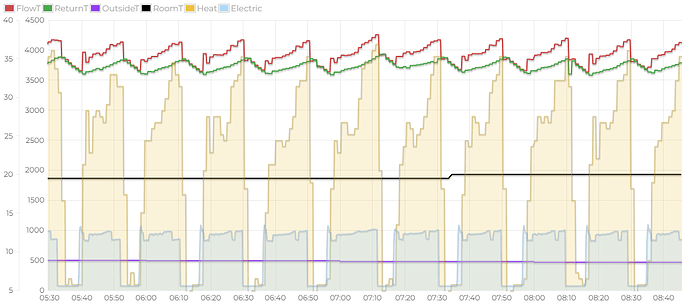
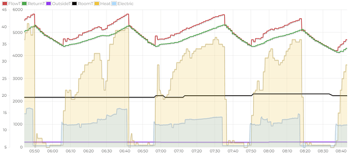
One thing I have been experimenting with, now that it has started to get colder, is pure WC and Auto-Adapt. I have the FTC6 main controller in our hallway so the room temp is measured by that, no other controls.
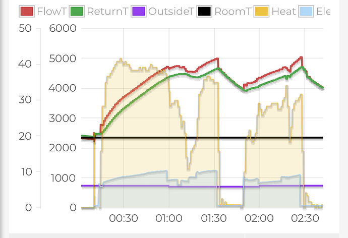
I have noticed that currently the Auto-Adapt appears to be a bit more efficient and produce longer runs, although this is likely due to it being happier to overshoot on Flow Temp than WC mode.
Weather Compensation:
Auto-Adapt:
Note the Auto-Adapt one shown is on a colder day but hitting slightly higher COP.
I know that my radiator area is currently undersized, mainly due to the huge K2 column radiator lying on its side in the hallway rather than being plumbed in (need to get around to painting the wall first).
Also it isn’t ideal that there currently are no emitters where the room temp is being read from so it probably takes longer to get feedback after applying heat.
Hopefully there will be improvements once that radiator is installed and I might get the plumber to increase the diameter of some of the primary pipework as well (easily accessed in the cellar) allowing higher flow rate (and less noise).
I have TRVs open fully downstairs and in the bathroom and ensuite. The bedroom TRVs are set to limit the temperature to 19.5C. Unfortunately the downstairs is the least insulated bit of the house so the bedroom TRVs are mostly closed most of the time and are likely to be until it gets properly cold outside.
I’ve been experimenting with a MelCloud schedule to drop the temperature by 0.5C at night and raise it by 0.5C on the Octopus Cosy off peak periods.
My system is here at HeatpumpMonitor.org. The overall COP figure has been hurt by problems measuring heat output for DHW that appear to be resolving themselves (mostly air related).
Any comments or suggestions about the behaviour of my system would be welcome.
Interesting observations Andrew. I have always liked Auto Adapt. For a lot of buildings and the way they are used, the outside temperature isnt always the best indicator of the best water target temperature.
One could spend house drilling into details, and one thing that interests me is this
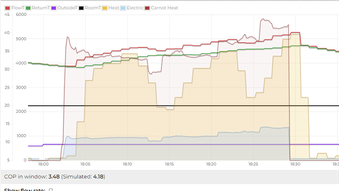
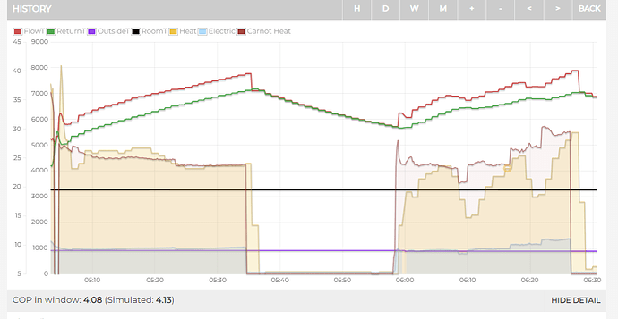
Its doing what my 6kw Ecodan was doing. I never got a sensible answer at all from Miitsubishi. The lighter ‘overlay’ is Trystans clever theoretical (carnot) COP. Theory, from air source here at 9.5C and flow temp say 35C, is that heat output should be at least 4kW (approx). However, the actual output dips considerably when the input is unchanged. I am certain that your discharge superheat (as ‘running information’ will tell you), drops to zero. Question I dont know the answer to is… whay does it do it sometimes?
We can then look at other times when it doesnt happen
Here, the theopretical COP is about in line with actual.
It would be nice to get to the bottom of this issue.
The only thing in the machine that varies aside from the compressor is the EEV, maybe it just chasing its tail at low output.
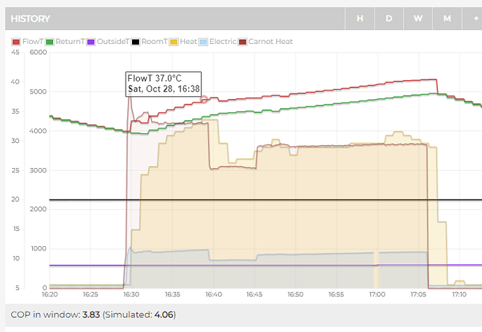
An example:
Just found another example on your system somewhere around 28th october. the left section has actual COP4.5 (simulated theoretcal 4.13) The right hand for some unknown reason has COP 3.7 (4.29 theopretical . Anyhow, bouth should be about the same, but its 18% worse! How many others are doing this??
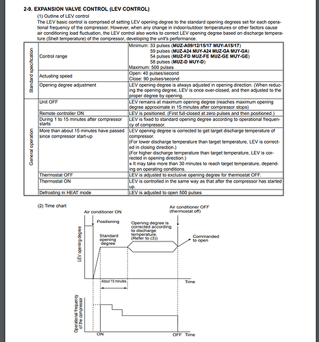
Is there any way to check what the LEV does when opening/closing?
“LEV opening degree is always adjusted in opening direction. When reducing the opening degree, LEV is once over-closed, and then adjusted to the proper degree by opening.”
This part could explain if it is what triggers the swings
Yes, exactly, it does sound like a refrigerant control issue (LEV or EEV as you say). On the Ecodan you can get ‘running information’ on the controller screen. this gives all sorts of ‘live’ values including all temperature sensors, the compressor speed, fan speed LEV position , water flow rate etc. The LEV positions can be observed, but control is automatic and not hackable. Mu hunch is that the sampling rate is not quick enough. Most of the time the 20 second (or whatever it is) sampling might be enough, but in certain conditions it could ‘hunt’, i.e. overreact and start oscilating. I’m guessing they need to sample for LEV control at twice the speed.
Hi Vinny, i missed this intesting page you found. I guess this is for an air conditioner? I have assumed that the starting position is dictated by a sort of look-up chart depending on temperture conditions. Surprised to see 15 min period before LEV modulation depending on discharge temperature. I’m sure my old Ecodan starts modulating the LEV fairly quickly after start. I could look at running information codes 022 ond 023 I think. Do these vary proportionally with compressor speed rise?
So, if the unit is cycling every 15 mins… it never has feed-back regulation? I suppose for AC, the raison-d’etre isnt to minimise energy, but an ASHP is.
I don’t think I’ve ever seen this happen on my Ecodan 11.2 kW running on R32. My heat output is noticebly lower during DHW cycles, but I don’t get the dips like you’ve shown here during space heating.
Think I’m going to have to read up on the components that make up the heat pump before I can understand all of this. Anyone know of a good explainer or an exploded diagram so I can see where all these valves etc sit?
I’m happy to do any investigations that might help.
