Anyone monitoring a new R32 Ecodan?

Hi, Here’s the hook-up arrangement. Use at your own risk obviously :slight_smile:
SikaFlowMeterHookUp.pdf (207.9 KB)
FlowMeterSketch.txt (3.6 KB)

Hope you don’t blow anything up…

Rachel

2 Likes

Thanks Rachel
I will have a look when I’m feeling brave
Mark

Can you share how you have set up control of your Ecodan 8.5kW and any settings you have changed?
Looking at how it is behaving it is doing a good job of continuous heating at a low level so would be interested to compare why our work’s office unit (same model) isn’t doing this.

Thanks for this Rachel, its useful to have detailed descriptions as starting points for those of us who bring zero experience to the task of setting up monitoring electronics.

You went route 1 and physically intervened in the wiring system. A less drastic solution was hinted at in another thread and has been expanded on by @TrystanLea in the documentation here: EmonTx4 Heatpump Monitor — OpenEnergyMonitor 0.0.1 documentation. The photos in part 3 show wires, doubled-up for some reason, in the block below where the Sika flow meter is plugged into the board. This bit of the technical docs shows the layout of the blocks at the bottom of the board and the reference to the flow meter at both locations – apparently allowing the Sika connector signal to be read from the lower block (I’m guessing that if you fit heat meters to the pipework this is where the flow data cables are wired in?).
FTC6 board.pdf (642.3 KB)

So far I have only got monitoring on the CU end of things, giving me the power consumption of my 8.5kW unit (which unlike Rachel’s seems to have a minimum working draw of around 1kW resulting in a lot more cycling unless it is decidedly cool).

I have yet to install at the cylinder unit end as I am still working up to the confidence to commit to programming an arduino-based solution to cope with several analogue readings and driving some 5V grundfoss sensors on the solar thermal. But soon, soon, …

In case it’s of some help to anyone: I can confirm that part of the TBI.4 block at the bottom of the FTC6 panel is wired in parallel with the flow sensor’s connector. I have a setup similar to Rachel’s, but measuring the voltage of pin 3 on that block relative to ground (pin 2).

I should probably introduce myself! I have had the 11.2 kW packaged unit installed for a bit over a year. I’ve noticed similar cycling issues to those discussed further up the thread, and have been progressively adding more monitoring to try to understand why it does this, given that you can see that it’s capable of modulating down far enough to avoid it.

Quite often the system gets in a cycle of ramping up aggressively, overshooting its target flow temperature, then abruptly stopping (or dropping to minimum power), waiting for a few minutes, then starting again. To me it just seems like a software problem: the hardware clearly could run consistently at an appropriate intermediate compressor speed – it’s just that the control system fails to find this speed in many circumstances.

3 Likes

Yes, I’ve seen this too. My solution is to limit the target flow temp to the return temp + 5 degrees (or whatever the optimal dT is for your system). This allows the heat pump to raise the temperature slowly without overshooting, and (maybe) reaching a steady state.

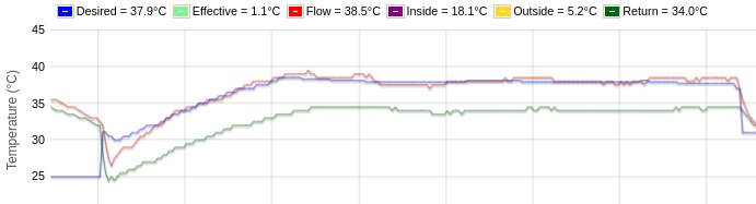
^ 6:30 until 10:30 am today. Compressor power was between 26% and 38% for this cycle, which is about as low as this unit* can go. [*EcoDan 11.2 kW]

This does require monitoring the heat pump very closely, and adjusting the flow temp every other minute. Here are some related threads that might provide interesting background:

3 Likes

That looks encouragingly stable! I’ll have a go at implementing something similar.

I suspect the issue is just the PID (proportional,Integral,Differential) parameters used by Mitsubishi in the flow temp control loop - set a bit too agressively leading to overshoot - I have seen the same on my 14 kw unit. Ramping up the setpoint is a good fix in the absence of being able to change the parameters of the control loop.

3 Likes

It continues to astounds me, that these very expensive systems appear to have such rudimentary control. Because 90% of the users never look at it, they get away with it! It really is scandalous.

It is almost as if they deliberately make it difficult to get the data out in case someone actually notices how rubbish they are!

Doesn’t lengthening the interval in the settings: heating operation: room temp control screen make it less aggressive? The default is just 10 minutes and few homes react that quickly.

This bit of the FTC6 manual…

…has the following footnotes:

*8 Valid only when operating in Room temp. control mode.
*10 Valid only when operating in Heating room temperature.
*15 When DIP SW5-2 is set to OFF, the function is active.

Where DIP SW5-2 is for “Advanced auto adaptation” and is on by default.

Unfortunately my system is in a tiny airing cupboard and reports the “room” to be 25 degrees all day, so room mode no use to me but maybe it’ll help someone else.

Its hard to understand all the subtleties isn’t it? I had intended to do proper experiments on Room Auto Adapt to get more familiar with exactly how it works, but not made time to do so. I think Flow temperature range limit works for all modes. I had considered using a resistor or some means to simulate the room temperure in order to make the unit do what you want. A bit crude. I have in the past strapped a resistor to a thermistor, and send a voltage to the resistor in order to ‘trick’ ‘offset’ the reading. There are simple crude ways that sometime work!

1 Like

Dont know - Im using weather comp rather than the room controller (mines in the airing cupboard!!)

1 Like

What is “the function” and what does it mean to be “active”? I think something has been lost in translation, or maybe the footnote is misplaced and should apply only to Mode, as Interval seems to affect Auto Adapt.

If you are in the UK, please let MCS know your installers were incompetent. Putting the thermometer in a cupboard wasn’t even a good idea with a fossil burning system, so it’s pretty inexcusable.

Where DIP SW5-2 is for “Advanced auto adaptation” and is on by default.

The thermometer is built in to the FTC unit, so that will be the default configuration. :man_shrugging:
The remote room controller is an optional extra. I’ve considered asking about having one fitted when I get bored with writing my own control code. If anyone has one of these, I’d be interested to hear how well it works in practice.

Edit: part number is PAR-WT50R-E, I think.

I’ve a two zone Ecodan system - both radiators/emitters rather than UFH - and I have remote controller in each.

I replaced two existing Nest thermostats and moved from weather compensation to room temp control mode which IMHO works much better, certainly in my circumstances.

2 Likes

I should clarify that my system was fitted with an external (dumb) room thermostat like a typical heating system, but this only sends a binary call for heat and doesn’t tell the FTC what the room temperature is and so the room mode isn’t able to respond accordingly.

The thermometer is in what’s shown on that page as “Ecodan controller” which I think is standard equipment and should be installed in a living area. It is not default to put it in a cupboard. That seems like ignorance, laziness or malice, all of which should be reported to the certification authority.

The room controller (main RC) has a thermistor, but there is also a thermistor option. I have never quite understood if TH1 does the same as main RC.
image

image

Easy to extend the main RC. mine is many metres away

2 Likes

Thanks John, that is useful. I might enquire to my installer about getting TH1 / PAC-SE41TS-E fitted.