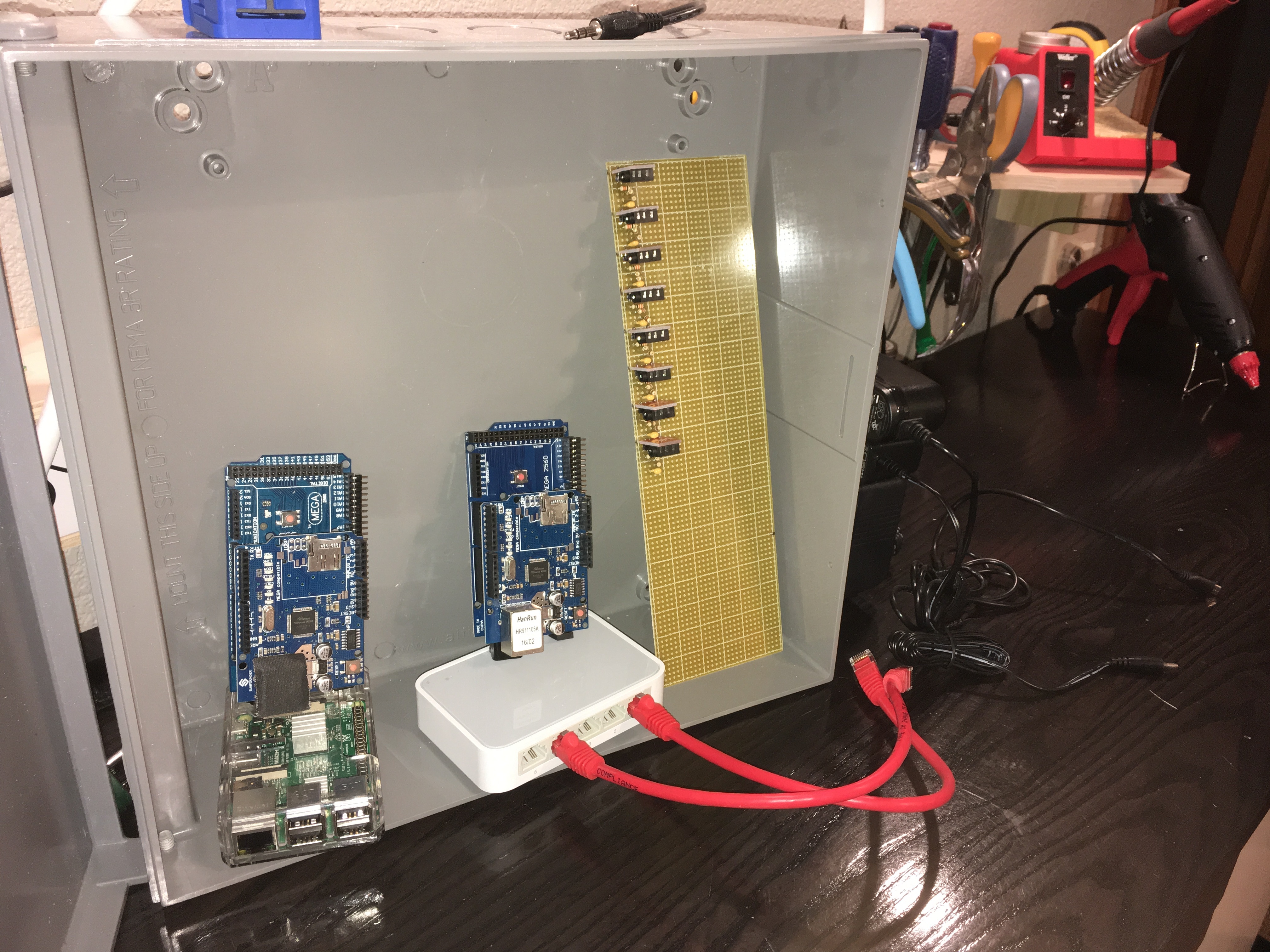
I’m finalizing plans of mounting things in the box, and am curious if I need to be cautious about running any of the analog wires near each other. Below is a pic of the box & components, as well as some info about my plan.
Analog Data Wires
Soldered from Arduino to stripboard (yes I will cut traces)
Since I’m running 2 Arduinos, there’s potential for 2 wires to be reading at the same time. Each Arduino can handle up to 15 sensors, and each Arduino will only be reading 1 sensor at a time. I don’t expect there to be much interference there, but that’s a very uneducated guess.
Aux wires from sensors
Will be entering the box through a hole in the back, and plugged into those ports
I realize these will be entering the load center box (main electric panel area) and running beside all of the house electrical wires. Is there risk of interference if noisy electronics are run? (I don’t see much of a way around this at this point)
I’m keeping the high voltage AC lines out of the box. The only power entering the box should be:
5V DC (power for Pi)
12V DC (power for Ethernet switch)
7.5V DC (power for Arduinos so the onboard regulators can clean properly)
9V AC (the AC-AC adapter).
The reason I’m concerned about interference is that I have a Pi / Arduino setup in another room, and the buttons are buggy when AC fans are running on that circuit (especially powered on).
Any advice would be greatly appreciated and worth far more than what I’m paying you.
The usual, and totally impractical, advice is never run two cables parallel with less than several metres spacing between them, and if you have to cross another wire, do so at right angles.
Seriously:
You’re looking at two ways that one circuit can interfere with another, electric fields and magnetic fields. Electric fields come from the voltage, magnetic fields from the current. Magnetic fields only really become a problem when they are changing, and the faster they change, the worse it gets.
So firstly, as you say, keep the high voltage cables that carry high currents away, as far as is practical.
Secondly, d.c. power supplies probably aren’t. They can easily be carrying a lot of high frequency components of current as the electronics they’re feeding generates switching transients. So treat these as if they have the plague and keep them away from anything sensitive.
Thirdly, make sure all common ground and earth connections are solid and more than adequate, so that what you think and hope is the same reference voltage (0 V, or GND) really is.
What sort of sensor are you talking about? What are the Aux Wires?
Unfortunately, some of the terms you’ve used are so general as to make it very hard for me to give any more than very general advice.
A circuit diagram, showing the boundaries of physical devices, would help.
Screening can be useful when done properly. Unfortunately, it often isn’t, for example, earthing a screen at the wrong end, or at both ends, can actually make things worse.
The c.t. secondary cables are screened, but there is no intentional connection of the screen anywhere. The 3.5 mm plug uses tip and sleeve for the signal, and the two cores are twisted. That alone should mean that any magnetic induction is kept to a minimum (because any field picked up in one half twist is cancelled by the next). The main way that a c.t. can pick up interference or crosstalk is from an adjacent current-carrying cable, especially if it passes close to the secondary winding, which is on the ‘bottom’ limb of the core. But it can also pick up the electric field by capacitive coupling, because the primary winding is very close to if not touching the secondary winding. Moving the c.t. onto the neutral (if it’s not shared) can help.
We think the main source of error, especially with the Arduino and front-end analogue sections built on prototype board, is digital noise from the processor itself getting into the ADC. We think the principal route may well be via the AREF pin, and there’s little you can do about that, as filtering on that depends on the design of the Arduino itself. Good decoupling on the feed to the bias networks, and as I mentioned good grounding, will be the key. It’s doubtful that screened cable from the burden resistor to the analogue input would do much, as the circuit impedance is quite low. But you need to make sure you keep the area of the loop small so as not to create a single-turn search coil for each input, so run the input wires and the corresponding 0 V connection close together.
There are some notes about this on the Atmel website, if my memory serves.
Also: http://www.analog.com/media/en/technical-documentation/application-notes/41727248AN_347.pdf
(Most of the semiconductor manufacturers of ADC will have useful application notes.)
Regarding the noise of the processor, I noticed that in my testing with a
single SCT. When the Arduino was powered by USB it was terrible (reading
30-60W with nothing attached). I added some capacitors and got it down to
maybe 15-30W. I tried a DC power supply, regulated to 5V with a buck
step-down converter, and got about the same results. BUT, using a cheap
power supply plugged in to the barrel jack (therefore using the linear
regulator of the Arduino) dropped that noise dramatically to well within a
strict margin of error.
I’ll continue the build and try to route wires appropriately per your
advice.