following your useful guides I made my electricity monitoring system with an Arduino, which has been working well for over a year
Now, if I find some time, I would like to improve the system a bit, by remaking the interface board, for example by implementing the “Buffered Voltage Bias” circuit.
In addition to this I have seen that someone add two 1n4148 protection diodes to the analog inputs, as in this example: Sharing the 2.5V reference, however according to some opinions they should be useless because Vf of the external diodes is likely to be higher than the internal Arduino diodes, which therefore would begin to conduct anyway sooner.
What could happen in my case is that the Arduino is switched off (temporarily) with connected measuring probes: what can I put as protection? I read on some forums to insert a resistance of 10k in series with the signal that applies to the analog pin, but does this not distort the measurement?
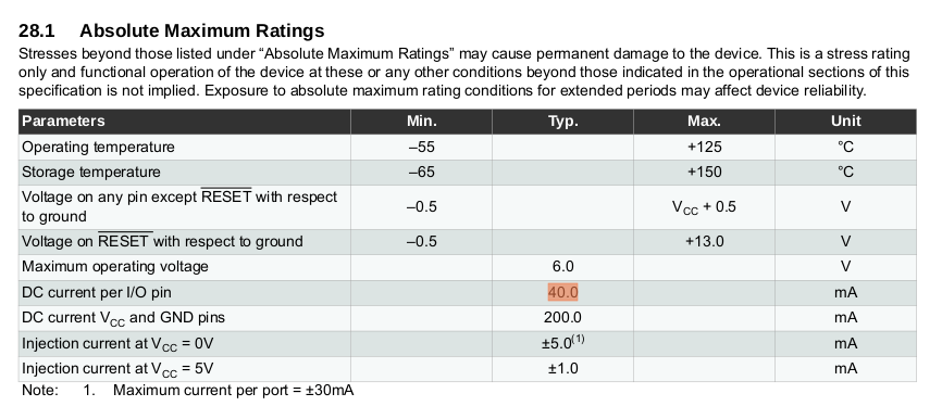
What you need to do depends on where you look. The ATMega 328P data sheet clearly states that the maximum input current per pin that the protection diodes can handle is 40 mA.
But if you check the Atmel Knowledge Base, there is an item there “I/O protection in XMEGA devices” which equally clearly states that:
“The protection mechanism is snapback diodes at each pad. The safe maximum current through this is 1mA.
The application note AVR182 shows an application example, which uses the I/O protection in Mega/Tiny devices.
For the source/sink capability of I/O pins, please refer the’ I/O Pin Characteristics’ section in the device datasheet.”
If you look at the App.Note AVR182, that recommends a 1 mA maximum current.
Therefore, there’s nothing wrong with having your own clamping diodes to limit the voltage to less than VCC+0.65 V and more than -0.65 V, then follow that with a series resistor (which can then of course be much less than 10 kΩ, as you’re only looking at a couple of hundred millivolts difference between the two diode voltages) to limit the current in, and thus protect, the internal clamping diodes. Your own protection diodes must of course be able to handle the maximum current that your sensors can provide.
You need to balance the series resistance needed to limit the current against the requirement to have a low source impedance/resistance for best measurement accuracy, which according to the data sheet for the '328P should be less than 10 kΩ.
My reading of that 40mA is that’s the current the pin can source (or sink) when it’s operating normally. In that case the 40mA won’t be flowing through protection diodes, but rather though the pin’s gate.
The injection current (1mA) is the relevant number in that table, and that’s consistent with the other references you listed - although it is a little more generous at 5mA when the device is not powered.
I’ve never managed to find “Injection current” on the Atmel 328P data sheet (Rev. 8161D–AVR–10/09 is the one I use, neither is it on Atmel-8271J-AVR- ATmega-Datasheet_11/2015). I did find the per port limit on a different (still Atmel) device, I can’t remember which now.
very interesting answers, I was clear about the limit of 40mA per pin and 200mA total, but not the others.
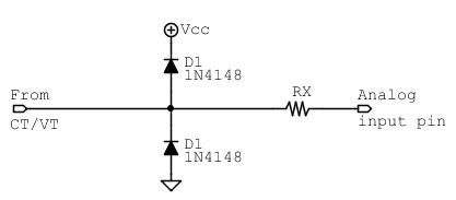
Therefore the scheme should be of the type:
where Rx must limit the current for the internal clamping diodes, at this point if I want to protect the Arduino even when turned on, the Imax is 1mA.
By setting Vfe and Vfi the forward voltage of the external and internal diodes respectively, Rx should have a minimum value of:
Rx min = (Vfe-Vfi)/0.001
whereas the 1N4148 diodes have a maximum of Vf=1V, while the internal ones are a minimum of 0.2V
Rx min = 800Ω
is correct?
The 1N4148 diodes have continuous forward current = 200mA, this should be more than enough…
Does resistance less than 1kΩ still guarantee an accurate measurement?
Would the proposed scheme protect arduino even if it is turned off with connected measuring probes?
This circuit could therefore be inserted in the guides, since with three miserable components the analog input is protected not only from the analog values out of range, but also from the Arduino off condition.
Rx could be composed of a series of two 330Ω and 470Ω resistors, more easily available.
Would it be better if the schottky 1N5817 were used instead of the 1N4148 diodes, with a much lower Vf?
True, and a single 820 Ω would be cheaper and easier to accommodate on the p.c.b., and the difference in the resistance value would be insignificant.
I suspect you’re thinking that it would allow a lower value for RX. Whilst that is true, I doubt if you would measure any appreciable difference in performance, since the series resistance is in any case much lower than the recommended limit of 10 kΩ, even when considering the voltage input; when that resistor is in series with equivalent resistance of the transformer and its voltage divider.
Have you thought about the impedance of that when feeding into the ADC? The adapter will have an effective series resistance of a few Ohms - using the published data for our adapter, it came to 3.88 Ω - and that is in series with the 100 kΩ. The Thévenin equivalent of that will be approx. 9.09 kΩ, so trying to make RX smaller won’t significantly affect the total value.
And in case you ask, I think the values were chosen to keep the overall power dissipation low.
For current measurements, I use SCT-013-000, with burden resistor calculated so as to have the maximum rated current plus 35% (in case of overload)
For the voltage measurement, the divider R values I have taken the suggested values, I have not evaluated the impedance, I imagine that they are high values to reduce the power dissipation, but we are not far from the 10kΩ limit recommended by Atmel, maybe they could have gone down a bit while obviously maintaining the 1:10 ratio?
For the c.t. input, the c.t. itself behaves as a current source with near-infinite impedance, so the source impedance of the current signal is effectively the burden.
For the voltage input, in theory adding a bigger load will reduce the flux in the core and reduce the distortion, so there might be a benefit to reducing the resistors’ values, though it’s hard to see that as being realistic with a transformer that’s got a full-load current of ½ A or more; it would require resistors dissipating several watts.
ok
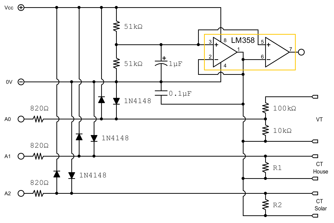
this would be the reference scheme for designing the pcb, is that correct?
did I connect port B of the LM358 like this, or is it better that I do not connect it at all?
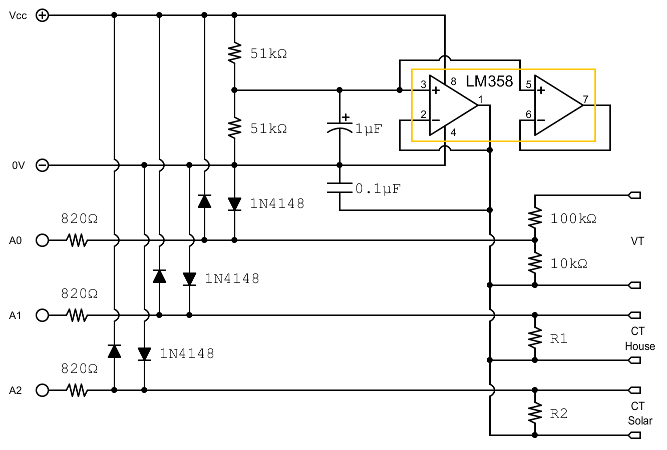
What you have drawn there is asking for problems. Connect the unused half exactly like you have the used half, i.e. connect pins 6 - 7, pin 5 is OK as it is. If you do not connect it at all, there’s a risk it will oscillate and consume excessive current.
Otherwise I can’t immediately see anything else that might cause a problem.