Hello, Can anyone point me in the right direction to connect the new all in one board to the controller.
Does it need to be programmed?
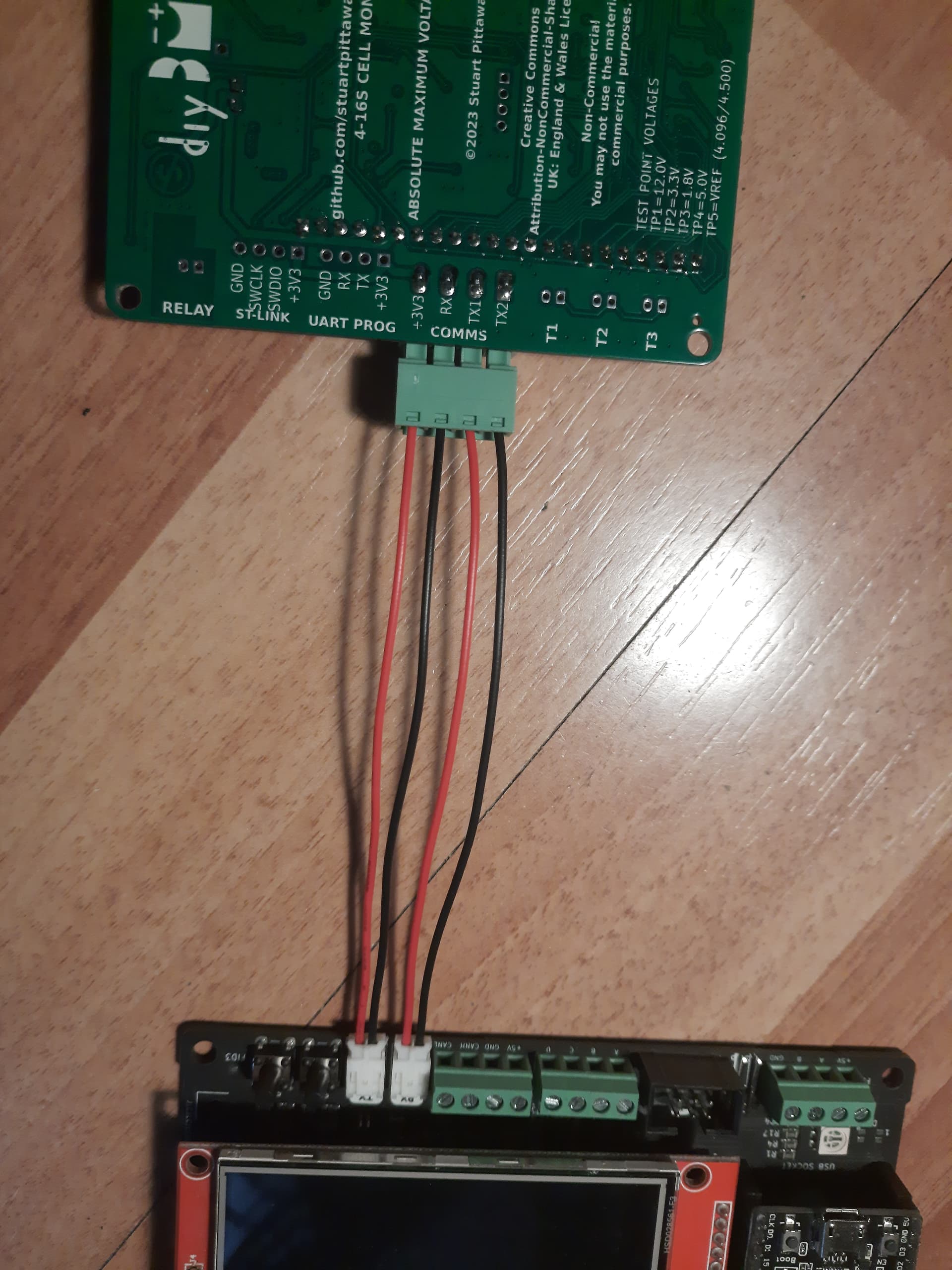
From vids I see 2 wires from all in one comms going to controller but where?
Is there a video I am missing or documents somewhere I cant find?
Ok all programmed. Now need to connect all in one to the controller.
All in one 5v ±…Where does this go? Does this connect to controller or to external 5v power?
All in one comms 4 pin connector. Where on controller does this connect?
Thanks for that photo. I’m working though my setup and it wasn’t really clear how the comm wiring was done. I’m just about ready to test everything I’m just waiting on that elusive 17pin connector to arrive so I can see it all work.
Hi. can anyone help me with my diybms
i have the 4.61 controller and all in one with passive balancing
both powering on ok.
connection of comms as per picture above, the all in one is blinking 3 times, which is correct
i connected 3 cells for test.
the problem is that the controller can not communicate to the module and sais waiting for modules.
if anybody can point me to the right direction that would be helpfull
kind regards
Thank You.
i have setup 16s and 1 bank, i do not have the cells connected just wanted to test communication.
will the comms work without the batteries connected ?
do i need to setup baudrate?