Adjust measurements

  1. Power consumption measured with CS4 on emontx3 is 25% wrong.
    When I measure the power consumption directly on the cable I measure 8.66 amps x 234 V = 2026W
    Emontx3 measures a power of 1500 W. See the yellow color at the Dashboard view
    Is it normal with such large measurement errors?

  2. It is possible to adjust the individual sensors in EmonHub, but the forum I read that I should adjust them in the sketch.

What difference does it make whether I make adjustments in EmonHub or emontx3’s sketch?
I have already adjust Vrms in the EmonHub.

[[8]]
nodename = emontx3
[[[rx]]]
names = power1, power2, power3, power4, vrms, temp1, temp2, temp3, temp4, temp5, temp6, pulse
datacodes = h,h,h,h,h,h,h,h,h,h,h,L
scales = 1,1,1,1,0.0087621,0.1,0.1, 0.1,0.1,0.1,0.1,1
units =W,W,W,W,V,C,C,C,C,C,C,p

  1. I read that there is developed a 3 phase sketch that I should upload to my emomtx3.
    What difference does it make if I measure 3 x single phases and summarize the effect, rather than using the dedicated 3 phase sketch?

There are no engines in the household, and hence no phase shift effect. The individual loads are made individually on different single phases (DENMARK).

  1. Is it possible to view the current directly on the emoncms from feeds for adjusting the CTs

  1. An error of that size is not right. It is possible, if you are very unlucky and have the worst possible set of components whose values are all at the extreme and wrong limit of the tolerance range, you could have an error of about 10% (see here) but normally, the components are not the worst possible set, errors in some at least partially cancel errors in others and the overall error is very much smaller. If you have the Euro ac adapter, then that will introduce an error because the voltage calibration for that is slightly different to the UK adapter, which is the default setting in the sketch (260 instead of 268.97 - which might account for 3.33% of your error).
    I think you should be looking for a fault, rather than a calibration error.

  2. There is indeed a 3-phase sketch. Unless a sketch has “3 phase” in the name, it is a single-phase sketch and unless all the CTs and the ac adapter measure the same phase, then the real power will be wrong for the CTs that are on different phases to the ac adapter. The apparent power will of course be correct.

  3. I prefer to calibrate the emonTx, but unless you are using a different CT or ac adaper to our standard and need to adjust the phase error calibration, there is no real difference between adjusting the calibration constant in the sketch and adjusting the scale in emonHub. But if you do set the scale in emonHub, remember that the voltage and power do NOT interact, so correcting the voltage will not at the same time correct the power, you must correct the power separately.

  4. Normally, the current values are not sent to the emonHub and so are not available to emonCMS. However, the current values area available in the sketch, and by editing it to add the currents to the “payload” and editing emonhub.conf likewise, you could display the currents.

How are you measuring that 8.66A? Is it with a true RMS ammeter? Assuming yes, and assuming your 234V measurement is also accurate, then the 2026W you’ve calculated is the apparent power. Since you have an AC adapter I’m assuming the 1500W reported by the emonTx is real power. If they were all perfectly accurate, that would represent a power factor of 0.74 which is certainly feasible depending on the nature of the combined loads.

AC motors aren’t the only source of phase shifts, and phase shifts aren’t the only source of non-unity power factors. My lighting circuit with a bunch of compact fluro bulbs has a power factor of 0.62 for example. What type of loads are on that circuit? Anything with a lot of switch mode power supplies like my compact fluro bulbs or any electronics such as TVs, computers etc. could be the cause of what you’re seeing (or transformers in low-voltage incandescent lighting).

Dear Robert Wall

I have done some research tonight

Definition of Real Power / RMS Power
I have studied definitonen of Real Power, RMS Power.

Alternating voltage ranges between 0 and about 325 V.
The power value / RMS value of 325 V is calculated as
peak (325V = square root of 2 * 230)
The square root of 2 = 1.4142
Thus reached the 230 Volt

It has decided to enter the alternating voltage to the value of the corresponding constant DC voltage that provides the same power (heat) in electrical resistance. It is called Vrms. Each measuring instrument is adapted to measure Vrms AC voltages, so there should be no particular order to carry out such measurement. I hope you agree?

Nissan Charger
As previously described, is a measurement of emontx on our charger for our Nissan Electric car, 33% too low, but I do not know of any. phase shift of the switch-mode charger built into the car.

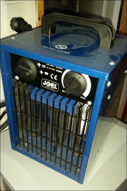
Electric Heater simulating Car Charger.
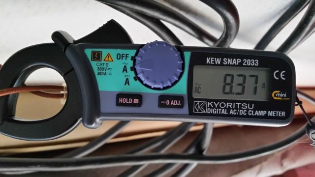
Therefore I test the same circuit just with a 2000 Watt heater, and measured the same way.
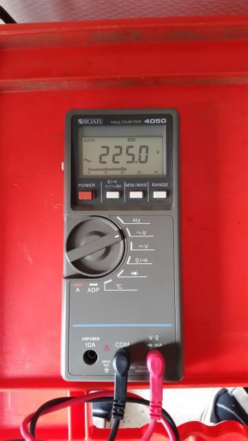
Here I get a measuring current of 8.37 A

The voltage at the test site is measured at 225, but emontx3 is measured at 230 V at the switchboard.

There are about 25 meters between the two points and with a load of this size, it is expected with a voltage drop of 5V
The calculated power is thus 8.37 x 225V = 1883.25 W

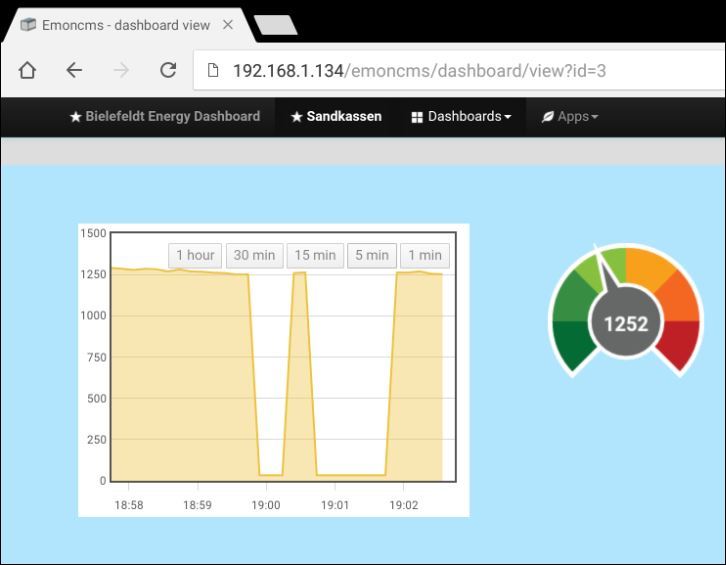
EmonTx3 and emonPi says 1252W on CT4 with max 4,5 kW
There must be corrected for the rest effect to a Network switch which run on the same group of 33W
So a total of 1219 W pure resistive load according emontx3.
A difference of 54% between the two measurements.
I have tried me with a second CT sensor, but it gives some same result.

I have adjusted Vrms down with the following calibration 0.0087621, to emontx3 to measure correctly AC value.

It would only bring power up to 1391 W if no calibration was inserted.

emonHUB
[[8]]
node name = emontx3
[[[Rx]]]
names = Power1, POWER2, ​​Power3, POWER4, Vrms, temp1, temp2, temp3, temp4, temp5, temp6, pulse
datacodes = h, h, h, h, h, h, h, h, h, h, h, L
scales = 1,1,1,1,0.0087621,0.1,0.1, 0.1,0.1,0.1,0.1,1
units = W, W, W, W, V, C, C, C, C, C, C, P

Alternative measure:

I have a Efergy energy meters installed as reference.
www.efergy.com, an English power measurement consumer company.

It measures the pulses via the electricity meter and displays power measurement in a display.
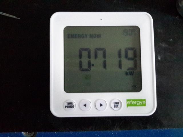
Efergy reading
I swipes Efergy to 719 W
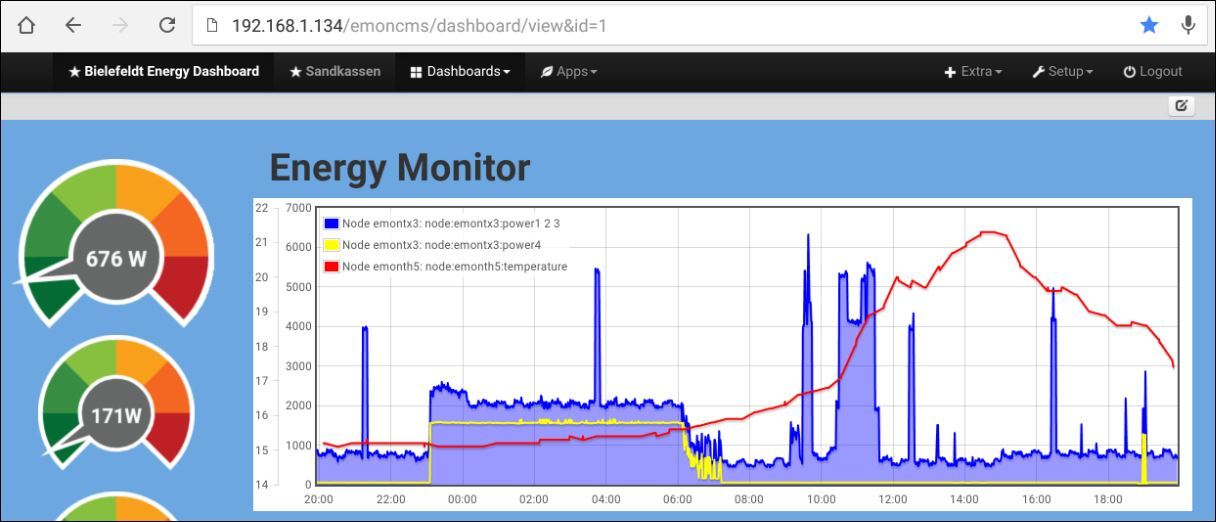
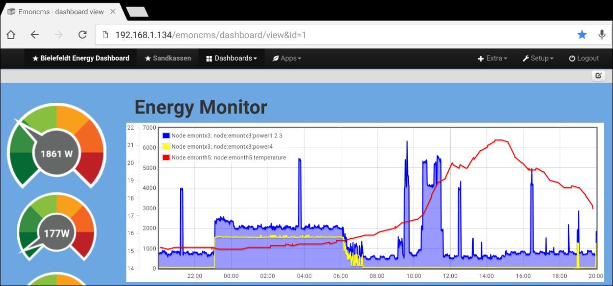
emontx3 reading
emontx3 read to 676W at the same time.

Power up heater
So I turn on my fan heater, and reads again after it has found a quiet level.
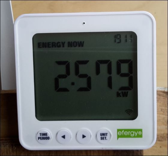
Efergy reading
Efergy read to 2579W a difference of 1860W, all very close to the 1883W I have measured and calculated with my instruments.

I thus has two independent measurements that says that my fan heater uses about 1860-1883W.
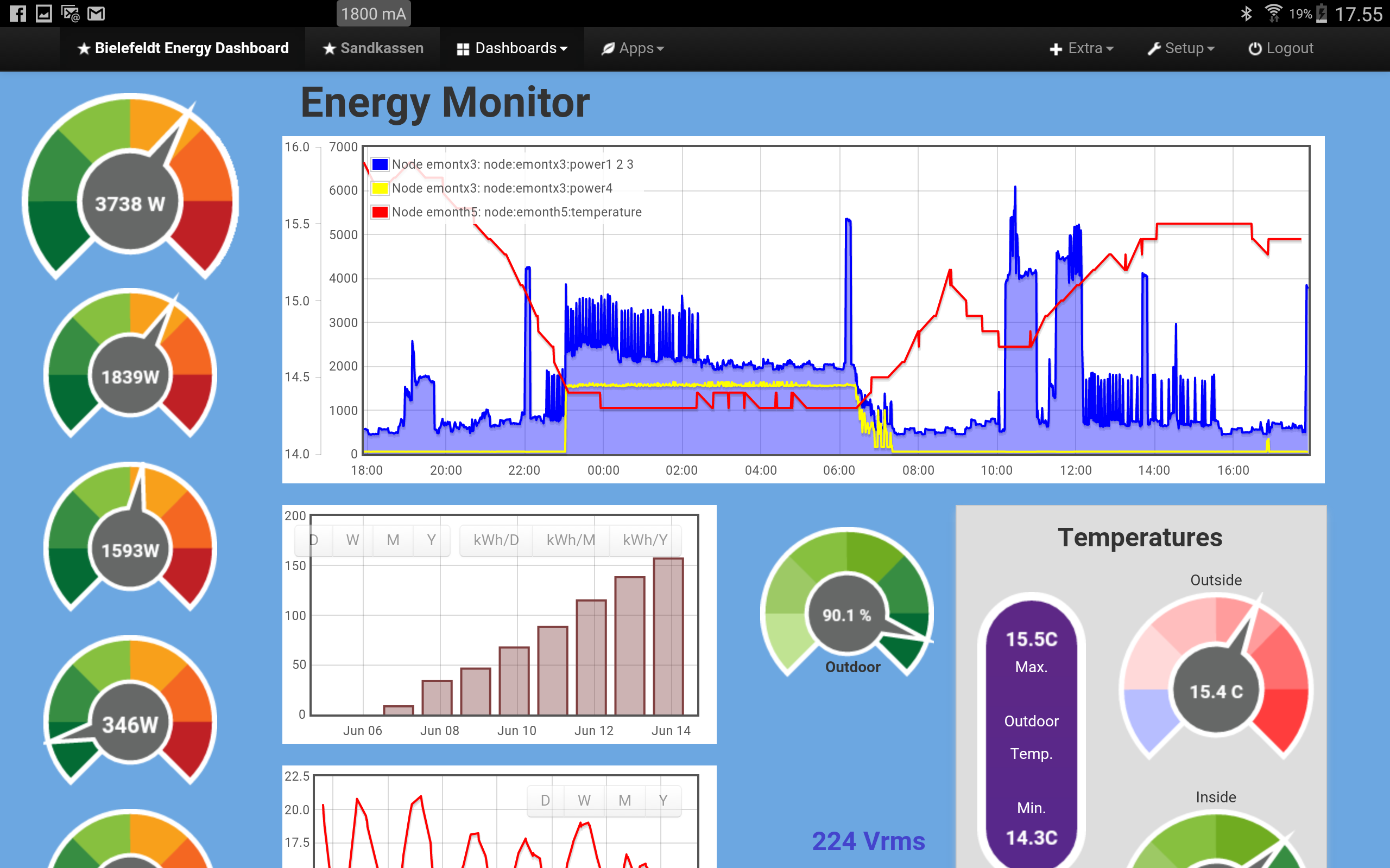
emontx3
emontx3 says while 1861W minus the prior reading 676W = 1185W, so close to the 1219W I previously measured.
The difference may be due to that one measurement is made with CT4, and the other with CT3.

Thus, there is a very big difference in the measured values.
Efergy and own measurements 1860-1883W
emontx3 1185 - 1219W
A difference of about 50%.

I am so bad frustrated that there is so great variation between the measured on emontx3 and I can measure and calculate manually.

I have an extra emontx3 and 4 additional CT sensors in stock, and I should like to try to replace them all to see if it makes any difference. There may indeed be a cause.

Hope you can figure out if I’m way off with some of my assumptions. Maybe I missed something.

Here are some thoughts:

Are you measuring voltage and current on the same phase of the supply? The standard emonTx sketch calculates real power only if the voltage and all 4 current measurements are made on the same phase. It does not, unless you have changed the sketch, send apparent power (which would be correct if voltage and current were measured on different phases) to the emonPi.

NIssan Charger.
As dBC writes, we do not know the power factor of the charger, therefore we cannot with certainty say that current × voltage = power. That might be true, but equally it might not be. We hope that Nissan have used a good design and that the power factor is good and close to 1, in which case that relationship will be true, or very nearly so.

Electric Heater Test.
We can be reasonably certain that the power factor will be close to 1, therefore current × voltage = power will be true in this case. We can also be reasonably certain that your KEW meter, although it appears not to read true rms, will be accurate within its specified range of ±1% ± 4 digits. (This means the actual current could be between 8.25 A and 8.49 A. The meter’s data sheet would say if it read true rms. It does not, so we must assume that it reads the rectified average and indicates the equivalent rms value assuming the wave shape is a pure sinusoid. That should not give a significant error with your heater, but it might with the sort of load that dBC warns about.)

The heater power you calculated does not include the power dissipated in your house wiring and lost as heat. It adds about 2.2% to the heater power you calculated, because the emonTx measures the voltage at your switchboard. You must measure at the same places to be able to compare accurately.

If you have tested a second CT and that is also wrong by nearly the same amount, that tells me that it is likely that the CT is not the problem.

“EmonTx3 and emonPi says 1252W” when the correct reading should be at least 1883 W.
Are you using the CT inputs on the emonPi to measure current, or are you saying that the emonPi is displaying the power measured by the emonTx?
If you are using the emonTx, is it possible to transfer the CT to the emonPi, and can you use that to measure the current of your heater instead of measuring it with the emonTx?

I should have asked this earlier: Is the CT closed correctly around the wire? The faces of the ferrite core must come together perfectly and there must be no air gap at all.

Dear Robert Wall

Thank you for your responses and inputs.

I make a new lab lineup tomorrow where I collect everything on a table. Documents all the measurements with images and tables.

My mind is to test the various CT sensors on the same power circuit from both emonPi emontx3 and at the same time, the use of resistive loads in the form of hot-air blower and lamps.

Have ordered a Fluke 117 True RMS Multimeter for checking voltages and currents. WIll you think it’s an okay choice for Vrms measurements?

So we will see what it brings.

Two things:
Your heater will have a blower motor in it, which should appear as a lagging power factor. However, with the heater load being about 2 kW, the presence of the motor should make no real difference to the overall power factor of the heater, so I would be happy to say that the power factor was 1.0 for practical purposes.
I did not evaluate the Fluke 117 when I wrote the Building Blocks page about multimeters but quickly looking at the specification, it will do everything that you want to calibrate your emonTx - both voltage and current. A warning though: read the manual before you measure a.c. current, because there is a limit on how long you can pass the maximum current before the meter will overheat and be damaged due to internal heating, there is probably a much lower current at which it is safe to operate continuously.