I have the “emonSD-30Oct18” running.
For energy, using a ADE9000 Energy Circuit that I have KWhr’s pulsing into
an Arduino Pulse counter sketch by Trystan, and tested by Glyn.
I also plan to add water and gas meter pulses to the Arduino Pulse counter.
This is using EmonHubTx3eInterfacer on com_port= /dev/ttyUSB0
The ADE9000 also has Volts/Amps/pF/temp/etc… available with a SPI Interface Read.
Ideally would like to use the same RPI3 Stretch that the EmonCMS is running on, to do the SPI Read from the ADE9000, then send to an emonhub socket interface.
Is the RPI3 running Emoncms able to handle SPI Reads, and some averaging and calibration calculations without affecting overall performance?
In addition, is there a recommended serial connection diagram for SPI Interface to a RPI3 running EmonCMS. Are the SPI_MOSI, SPI_MISO, and SPI_CLK available?
Is there any sample code doing a SPI_READ available for a RPI3 running EmonCMS?
An RPi running emoncms is an RPi running Linux, so you should be able to use any of the standard Linux/RPi tutorials on doing SPI, something like SPI.
Do you have any details on your “ADE9000 Energy Circuit”? How does it sense V? I’m guessing with the standard resistor divider directly connected to each phase? You might be aware of this already, but in case not it’s vital that you use some sort of isolation (typically opto-isolators) between that device and your RPi or the whole lot can easily end up lethally live.
I’ve done a lot of ADE SPI programming on embedded AVRs and stm32s, but not on Linux. I vaguely recall back in 2012 I may have hooked up one of their eval boards (which comes with isolators) to a RPi to experiment with Linux SPI programming, but I never pursued it seriously. I can’t immediately find the code, but if you get stuck after reading the above SPI programming tips ask again and I’ll look harder.
Thanks for recommending isolation. I haven’t thought about it much,
but will need to address it before deployment.
I was thinking of SPI isolation, and an isolated 3.3vdc power supply.
That way, would just loose the ADE9000, but the rest should survive.
Do you have a recommendation for isolation?
I hope the SPI code doesn’t over burden the RPi running emoncms.
The SPI code will have to include some calibration constants and
do some averaging. Any experience on the performance of a Emon RPI when implementing
SPI on the same RPI that the EmonCMS is running on?
That test circuit is fine, it’s all low voltage. The only thing they have put on the analog inputs are anti-aliasing filters. That test circuit is designed for lab testing on a signal generator with voltages in the +/- 1V ballpark.
That breakout board however goes one step further and connects it to the grid by way of 1M/1K dividers on each phase. There doesn’t appear to be any isolation on that at all, unless it’s on the back side of the board? Assuming there isn’t, that board should be illegal, or come with some serious health warnings. If your neutral drops off, the entire setup (including your RPi via the SPI bus) will be sitting at mains voltage. The 1M resistor might offer some protection, but it would still hurt, and if that were to fail to a short you’re dead.
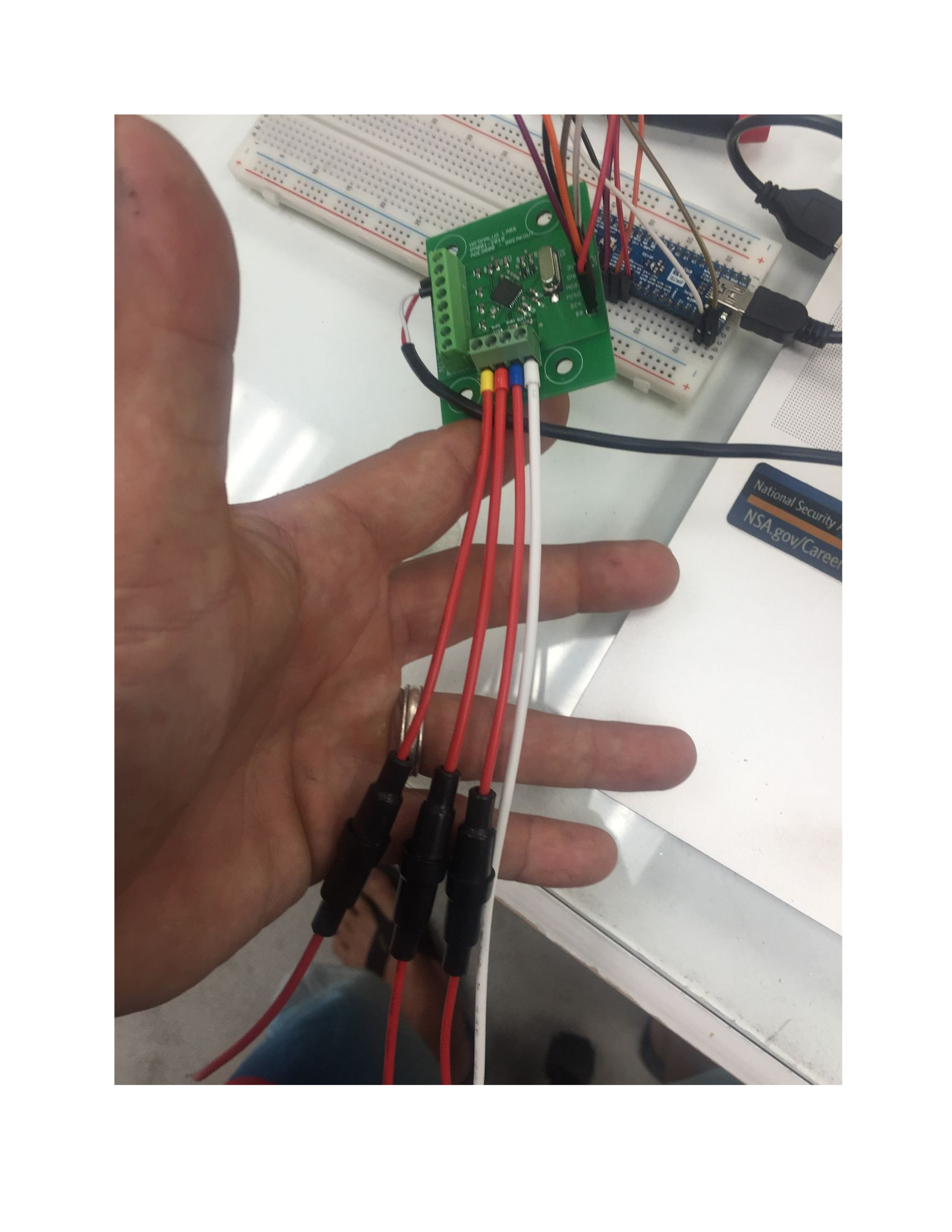
Unless you’re very experienced with working with live mains connected equipment I would throw it in the bin. This picture from their github page seems mind-blowingly irresponsible:
I am familiar working with high voltages. This is NOT a commercial product; it is for my personal residential use only! I am using a PC817C Opt isolator to isolate the pulse, and plan on using a SPI Isolator to cover the SPI bus. After development, the ADE9000 Breakout, RPI, and Arduino will all be in a bonded metal box.
Consider that the complete system will be in a secure bonded metal box. Then, if I understand the concerns correctly, a grounded neutral dropping off an ISOLATED ADE9000 Breakout should NOT be a health hazard, or destroy the rest of the RPI system, but may have an adverse effect on the ADE9000. In addition, if the neutral drops off by our Electrical provider, I believe there would be bigger problems then the isolated ADE9000 Breakout in a bonded metal box.
Again, I am concerned whether the RPI3 performance will degrade when using SPI on a running Emoncms on the same RPI3. So, if there is anyone who already implemented SPI on a RPI3 running Emoncms I would appreciate feedback whether this is a possibility. Otherwise I will consider the built-in RFMxxx wireless Interface.
You might want to start by asking Hoomaluo Labs what safety testing they’ve done. It’s hard to be sure from a photo but those incoming phase lines look a bit close for something that’s going to have 415V across it. If arcing were to break out there it could get pretty exciting.
And I’m pretty sure if you were coding it up as per that photo above when the Neutral went away, your laptop would be at mains voltage. You really need the isolation in place while you’re doing the development.
Not something I have any experience with, but my gut feel is that shouldn’t be an issue. It’s all user level code (apart from a bit of SPI driver kernel code) running on a general purpose computer with a general purpose OS. If things get busy the scheduler will do its stuff and all the processes will just run a bit slower, but I’d be amazed if you can even notice the odd SPI transaction on emoncms performance. Even if you were to code it with lots of busy wait loops, you can just ‘nice’ your process to a lower priority than Apache - not that you should as that would make your RPi run hotter.
No, when I say “our ADE based monitor” I should have said “my ADE based monitor” but that would have excluded my collaborator. It’s not related to OEM, and is neither open nor commercial. There’s a pic of it here.
I asked the engineer who designed this to cast an eye over that breakout board. Here’s what came back…
The more I think of that ADE9000 breakout board the more it disturbs me. Looking at the photo, the 1Mohm resistors look like 0603 size (1.6x0.8mm). They typically have a working voltage rating of 75V and a maximum overload of 150V. In their design that is a single component that has 375V peak across it. On top of that the spacing on the PCB is a serious concern. For 230V stuff it is common to have 1.5mm between traces after some sort of protection (ie a fuse). For the traces before a fuse or other protection you would double that to 3mm.
For 415V you would double that again. That is why our monitor has larger connectors for the V and big spacing and 4 resistors in series for the voltage divider. For safety testing the inspector is allowed to short out any single component and in doing so the design must not catch fire or present a safety risk.
Also, for reinforced insulation up to 300V you need at least 6.4mm of clearance. Each 0603 resistor gives you approx 0.8mm clearance between the copper pads. Again that is 230VAC across 0.8mm Not much security at all. In our monitor I have four big resistors (1206 I think). They each have a higher voltage rating due to size (200V) and the pads have a 2mm separation giving me 8mm in total - the same as the isolation gap between safe and high voltage sides in other parts of the board.
The 5mm connectors they are using also don’t have the voltage rating or physical clearance for 415V 3-phase. They are rated and have clearance for 230V (ie less than 300V working voltage), but for 3-phase you need 7.5mm connectors and appropriate spacing between pads on the PCB.
