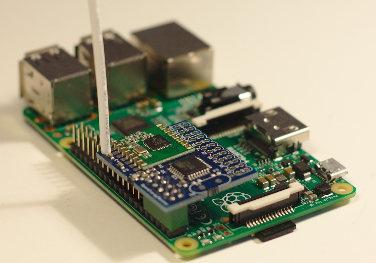
And here is the firmware I have running on my emonTx v.3
/*

  emonTxV3.4 Discrete Sampling

  If AC-AC adapter is detected assume emonTx is also powered from adapter (jumper shorted) and take Real Power Readings and disable sleep mode to keep load on power supply constant
  If AC-AC addapter is not detected assume powering from battereis / USB 5V AC sample is not present so take Apparent Power Readings and enable sleep mode

  Transmitt values via RFM69CW radio

   -----------------------------------------
  Part of the openenergymonitor.org project

  Authors: Glyn Hudson & Trystan Lea
  Builds upon JCW JeeLabs RF12 library and Arduino

  Licence: GNU GPL V3

*/

/*Recommended node ID allocation
------------------------------------------------------------------------------------------------------------
-ID-	-Node Type-
0	- Special allocation in JeeLib RFM12 driver - reserved for OOK use
1-4     - Control nodes
5-10	- Energy monitoring nodes
11-14	--Un-assigned --
15-16	- Base Station & logging nodes
17-30	- Environmental sensing nodes (temperature humidity etc.)
31	- Special allocation in JeeLib RFM12 driver - Node31 can communicate with nodes on any network group
-------------------------------------------------------------------------------------------------------------


Change Log:
v2.3   16/11/15 Change to unsigned long for pulse count and make default node ID 8 to avoid emonHub node decoder conflict & fix counting pulses faster than 110ms, strobed meter LED http://openenergymonitor.org/emon/node/11490
v2.2   12/11/15 Remove debug timming serial print code
v2.1   24/10/15 Improved timing so that packets are sent just under 10s, reducing resulting data gaps in feeds + default status code for no temp sensors of 3000 which reduces corrupt packets improving data reliability
V2.0   30/09/15 Update number of samples 1480 > 1662 to improve sampling accurancy: 1662 samples take 300 mS, which equates to 15 cycles @ 50 Hz or 18 cycles @ 60 Hz.
V1.9   25/08/15 Fix spurious pulse readings from RJ45 port when DS18B20 but no pulse counter is connected (enable internal pull-up)
V1.8 - 18/06/15 Increase max pulse width to 110ms
V1.7 - 12/06/15 Fix pulse count debounce issue & enable pulse count pulse temperature
V1.6 - Add support for multiple DS18B20 temperature sensors
V1.5 - Add interrupt pulse counting - simplify serial print debug
V1.4.1 - Remove filter settle routine as latest emonLib 19/01/15 does not require
V1.4 - Support for RFM69CW, DIP switches and battery voltage reading on emonTx V3.4
V1.3 - fix filter settle time to eliminate large inital reading
V1.2 - fix bug which caused Vrms to be returned as zero if CT1 was not connected
V1.1 - fix bug in startup Vrms calculation, startup Vrms startup calculation is now more accuratre
*/

#define emonTxV3                                                                          // Tell emonLib this is the emonTx V3 - don't read Vcc assume Vcc = 3.3V as is always the case on emonTx V3 eliminates bandgap error and need for calibration http://harizanov.com/2013/09/thoughts-on-avr-adc-accuracy/
#define RF69_COMPAT 1                                                              // Set to 1 if using RFM69CW or 0 is using RFM12B
#include <JeeLib.h>
ISR(WDT_vect) { Sleepy::watchdogEvent(); }                            // Attached JeeLib sleep function to Atmega328 watchdog -enables MCU to be put into sleep mode inbetween readings to reduce power consumption

#include "EmonLib.h"                                                                    // Include EmonLib energy monitoring library
EnergyMonitor ct1, ct2, ct3, ct4;

#include "OneWire.h"
#include <DallasTemperature.h>


const byte version = 232;         // firmware version divided by 10 e,g 16 = V1.6

//----------------------------emonTx V3 Settings---------------------------------------------------------------------------------------------------------------
const byte Vrms=                  230;                               // Vrms for apparent power readings (when no AC-AC voltage sample is present)
const byte TIME_BETWEEN_READINGS = 10;            //Time between readings

//http://openenergymonitor.org/emon/buildingblocks/calibration

const float Ical1=                90.9;                                 // (2000 turns / 22 Ohm burden) = 90.9
const float Ical2=                90.9;                                 // (2000 turns / 22 Ohm burden) = 90.9
const float Ical3=                90.9;                                 // (2000 turns / 22 Ohm burden) = 90.9
const float Ical4=                16.67;                               // (2000 turns / 120 Ohm burden) = 16.67

float Vcal=                       268.97;                             // (230V x 13) / (9V x 1.2) = 276.9 Calibration for UK AC-AC adapter 77DB-06-09
//float Vcal=276.9;
//const float Vcal=               260;                             //  Calibration for EU AC-AC adapter 77DE-06-09
const float Vcal_USA=             130.0;                             //Calibration for US AC-AC adapter 77DA-10-09
boolean USA=FALSE;

const float phase_shift=          1.7;
const int no_of_samples=          1662;
const int no_of_half_wavelengths= 30;
const int timeout=                2000;                               //emonLib timeout
const int ACAC_DETECTION_LEVEL=   3000;
const byte min_pulsewidth= 110;                                // minimum width of interrupt pulse (default pulse output meters = 100ms)
const int TEMPERATURE_PRECISION=  11;                          //9 (93.8ms),10 (187.5ms) ,11 (375ms) or 12 (750ms) bits equal to resplution of 0.5C, 0.25C, 0.125C and 0.0625C
const byte MaxOnewire=             6;
#define ASYNC_DELAY 375                                          // DS18B20 conversion delay - 9bit requres 95ms, 10bit 187ms, 11bit 375ms and 12bit resolution takes 750ms
//-------------------------------------------------------------------------------------------------------------------------------------------
//-------------------------------------------------------------------------------------------------------------------------------------------


//----------------------------emonTx V3 hard-wired connections---------------------------------------------------------------------------------------------------------------
const byte LEDpin=                 6;                              // emonTx V3 LED
const byte DS18B20_PWR=            19;                             // DS18B20 Power
const byte DIP_switch1=            8;                              // Voltage selection 230 / 110 V AC (default switch off 230V)  - switch off D8 is HIGH from internal pullup
const byte DIP_switch2=            9;                              // RF node ID (default no chance in node ID, switch on for nodeID -1) switch off D9 is HIGH from internal pullup
const byte battery_voltage_pin=    7;                              // Battery Voltage sample from 3 x AA
const byte pulse_countINT=         1;                              // INT 1 / Dig 3 Terminal Block / RJ45 Pulse counting pin(emonTx V3.4) - (INT0 / Dig2 emonTx V3.2)
const byte pulse_count_pin=        3;                              // INT 1 / Dig 3 Terminal Block / RJ45 Pulse counting pin(emonTx V3.4) - (INT0 / Dig2 emonTx V3.2)
#define ONE_WIRE_BUS               5                               // DS18B20 Data
//-------------------------------------------------------------------------------------------------------------------------------------------

//Setup DS128B20
OneWire oneWire(ONE_WIRE_BUS);
DallasTemperature sensors(&oneWire);
byte allAddress [MaxOnewire][8];  // 8 bytes per address
byte numSensors;
//-------------------------------------------------------------------------------------------------------------------------------------------

//-----------------------RFM12B / RFM69CW SETTINGS----------------------------------------------------------------------------------------------------
#define RF_freq RF12_433MHZ                                              // Frequency of RF69CW module can be RF12_433MHZ, RF12_868MHZ or RF12_915MHZ. You should use the one matching the module you have.
byte nodeID = 8;                                                        // emonTx RFM12B node ID
const int networkGroup = 210;

typedef struct {
  int power1, power2, power3, power4, Vrms, temp[MaxOnewire];
  unsigned long pulseCount;
} PayloadTX;     // create structure - a neat way of packaging data for RF comms

PayloadTX emontx;

//-------------------------------------------------------------------------------------------------------------------------------------------
//-------------------------------------------------------------------------------------------------------------------------------------------

//Random Variables
//boolean settled = false;
boolean CT1, CT2, CT3, CT4, ACAC, debug, DS18B20_STATUS;
byte CT_count=0;
volatile byte pulseCount = 0;
unsigned long pulsetime=0;                                    // Record time of interrupt pulse
void setup()
{
  pinMode(LEDpin, OUTPUT);
  pinMode(DS18B20_PWR, OUTPUT);

  pinMode(pulse_count_pin, INPUT_PULLUP);                     // Set emonTx V3.4 interrupt pulse counting pin as input (Dig 3 / INT1)
  emontx.pulseCount=0;                                        // Make sure pulse count starts at zero

  digitalWrite(LEDpin,HIGH);

  Serial.begin(9600);

  Serial.print("emonTx V3.4 Discrete Sampling V"); Serial.print(version*0.1);
  #if (RF69_COMPAT)
    Serial.println(" RFM69CW");
  #else
    Serial.println(" RFM12B");
  #endif
  Serial.println("OpenEnergyMonitor.org");
  Serial.println("POST.....wait 10s");

  //READ DIP SWITCH POSITIONS
  pinMode(DIP_switch1, INPUT_PULLUP);
  pinMode(DIP_switch2, INPUT_PULLUP);
  if (digitalRead(DIP_switch1)==LOW) nodeID--;                            // IF DIP switch 1 is switched on then subtract 1 from nodeID
  if (digitalRead(DIP_switch2)==LOW) USA=TRUE;                            // IF DIP switch 2 is switched on then activate USA mode


  if (USA==TRUE){                                                         // if USA mode is true
    Vcal=Vcal_USA;                                                        // Assume USA AC/AC adatper is being used, set calibration accordingly
  }

  delay(10);
  rf12_initialize(nodeID, RF_freq, networkGroup);                         // initialize RFM12B/rfm69CW
  for (int i=10; i>=0; i--)                                               // Send RF test sequence (for factory testing)
  {
    emontx.power1=i;
    rf12_sendNow(0, &emontx, sizeof emontx);
    delay(100);
  }
  rf12_sendWait(2);
  emontx.power1=0;

  if (analogRead(1) > 0) {CT1 = 1; CT_count++;} else CT1=0;              // check to see if CT is connected to CT1 input, if so enable that channel
  if (analogRead(2) > 0) {CT2 = 1; CT_count++;} else CT2=0;              // check to see if CT is connected to CT2 input, if so enable that channel
  if (analogRead(3) > 0) {CT3 = 1; CT_count++;} else CT3=0;              // check to see if CT is connected to CT3 input, if so enable that channel
  if (analogRead(4) > 0) {CT4 = 1; CT_count++;} else CT4=0;              // check to see if CT is connected to CT4 input, if so enable that channel

  if ( CT_count == 0) CT1=1;                                             // If no CT's are connect ed CT1-4 then by default read from CT1

  // Quick check to see if there is a voltage waveform present on the ACAC Voltage input
  // Check consists of calculating the RMS from 100 samples of the voltage input.
  Sleepy::loseSomeTime(10000);            //wait for settle
  digitalWrite(LEDpin,LOW);

  // Calculate if there is an ACAC adapter on analog input 0
  //double vrms = calc_rms(0,1780) * (Vcal * (3.3/1024) );
  double vrms = calc_rms(0,1780) * 0.87;
  if (vrms>90) ACAC = 1; else ACAC=0;

  if (ACAC)
  {
    for (int i=0; i<10; i++)                                              // indicate AC has been detected by flashing LED 10 times
    {
      digitalWrite(LEDpin, HIGH); delay(200);
      digitalWrite(LEDpin, LOW); delay(300);
    }
  }
  else
  {
    delay(1000);
    digitalWrite(LEDpin, HIGH); delay(2000); digitalWrite(LEDpin, LOW);   // indicate DC power has been detected by turing LED on then off
  }


  //################################################################################################################################
  //Setup and for presence of DS18B20
  //################################################################################################################################
  digitalWrite(DS18B20_PWR, HIGH); delay(100);
  sensors.begin();
  sensors.setWaitForConversion(false);             // disable automatic temperature conversion to reduce time spent awake, conversion will be implemented manually in sleeping

  numSensors=(sensors.getDeviceCount());
  if (numSensors > MaxOnewire) numSensors=MaxOnewire;   //Limit number of sensors to max number of sensors

  byte j=0;                                        // search for one wire devices and
                                                   // copy to device address arrays.
  while ((j < numSensors) && (oneWire.search(allAddress[j])))  j++;

  delay(500);
  digitalWrite(DS18B20_PWR, LOW);

  if (numSensors==0) DS18B20_STATUS=0;
    else DS18B20_STATUS=1;

  //################################################################################################################################

  if (Serial) debug = 1; else debug=0;          // if serial UART to USB is connected show debug O/P. If not then disable serial
  if (debug==1)
  {
    Serial.print("CT 1 Cal "); Serial.println(Ical1);
    Serial.print("CT 2 Cal "); Serial.println(Ical2);
    Serial.print("CT 3 Cal "); Serial.println(Ical3);
    Serial.print("CT 4 Cal "); Serial.println(Ical4);
    delay(1000);

    Serial.print("RMS Voltage on AC-AC  is: ~");
    Serial.print(vrms,0); Serial.println("V");

    if (ACAC) {
      Serial.println("AC-AC detected - Real Power measure enabled");
      Serial.println("assuming pwr from AC-AC (jumper closed)");
      if (USA==TRUE) Serial.println("USA mode active");
      Serial.print("Vcal: "); Serial.println(Vcal);
      Serial.print("Phase Shift: "); Serial.println(phase_shift);
    } else {
      Serial.println("AC-AC NOT detected - Apparent Pwr measure enabled");
      Serial.print("Assuming VRMS: "); Serial.print(Vrms); Serial.println("V");
      Serial.println("Assuming power from batt / 5V USB - power save enabled");
    }

    if (CT_count==0) {
      Serial.println("NO CT's detected");
    } else {
      if (CT1) Serial.println("CT 1 detected");
      if (CT2) Serial.println("CT 2 detected");
      if (CT3) Serial.println("CT 3 detected");
      if (CT4) Serial.println("CT 4 detected");
    }

    if (DS18B20_STATUS==1) {
      Serial.print("Detected Temp Sensors:  ");
      Serial.println(numSensors);
    } else {
      Serial.println("No temperature sensor");
    }

    #if (RF69_COMPAT)
       Serial.println("RFM69CW");
    #else
      Serial.println("RFM12B");
    #endif

    Serial.print("Node: "); Serial.print(nodeID);
    Serial.print(" Freq: ");
    if (RF_freq == RF12_433MHZ) Serial.print("433Mhz");
    if (RF_freq == RF12_868MHZ) Serial.print("868Mhz");
    if (RF_freq == RF12_915MHZ) Serial.print("915Mhz");
    Serial.print(" Network: "); Serial.println(networkGroup);

    Serial.print("NODE CT1 CT2 CT3 CT4 VRMS/BATT PULSE");
    if (DS18B20_STATUS==1){Serial.print(" Temperature 1-"); Serial.print(numSensors);}
    Serial.println(" ");
    delay(500);

  }
  else
  {
    Serial.end();
  }


  if (CT1) ct1.current(1, Ical1);             // CT ADC channel 1, calibration.  calibration (2000 turns / 22 Ohm burden resistor = 90.909)
  if (CT2) ct2.current(2, Ical2);             // CT ADC channel 2, calibration.
  if (CT3) ct3.current(3, Ical3);             // CT ADC channel 3, calibration.
  if (CT4) ct4.current(4, Ical4);             // CT ADC channel 4, calibration.  calibration (2000 turns / 120 Ohm burden resistor = 16.66) high accuracy @ low power -  4.5kW Max @ 240V

  if (ACAC)
  {
    if (CT1) ct1.voltage(0, Vcal, phase_shift);          // ADC pin, Calibration, phase_shift
    if (CT2) ct2.voltage(0, Vcal, phase_shift);          // ADC pin, Calibration, phase_shift
    if (CT3) ct3.voltage(0, Vcal, phase_shift);          // ADC pin, Calibration, phase_shift
    if (CT4) ct4.voltage(0, Vcal, phase_shift);          // ADC pin, Calibration, phase_shift
  }

  attachInterrupt(pulse_countINT, onPulse, FALLING);     // Attach pulse counting interrupt pulse counting

  for(byte j=0;j<MaxOnewire;j++)
      emontx.temp[j] = 3000;                             // If no temp sensors connected default to status code 3000
                                                         // will appear as 300 once multipled by 0.1 in emonhub
} //end SETUP

void loop()
{
  unsigned long start = millis();

  if (ACAC) {
    delay(200);                         //if powering from AC-AC allow time for power supply to settle
    emontx.Vrms=0;                      //Set Vrms to zero, this will be overwirtten by CT 1-4
  }

  // emontx.power1 = 1;
  // emontx.power2 = 1;
  // emontx.power3 = 1;
  // emontx.power4 = 1;

  if (CT1) {
    if (ACAC) {
      ct1.calcVI(no_of_half_wavelengths,timeout); emontx.power1=ct1.realPower;
      emontx.Vrms=ct1.Vrms*100;
    } else {
      emontx.power1 = ct1.calcIrms(no_of_samples)*Vrms;                               // Calculate Apparent Power 1  1480 is  number of sample
    }
  }

  if (CT2) {
    if (ACAC) {
      ct2.calcVI(no_of_half_wavelengths,timeout); emontx.power2=ct2.realPower;
      emontx.Vrms=ct2.Vrms*100;
    } else {
      emontx.power2 = ct2.calcIrms(no_of_samples)*Vrms;                               // Calculate Apparent Power 1  1480 is  number of samples
    }
  }

  if (CT3) {
    if (ACAC) {
      ct3.calcVI(no_of_half_wavelengths,timeout); emontx.power3=ct3.realPower;
      emontx.Vrms=ct3.Vrms*100;
    } else {
      emontx.power3 = ct3.calcIrms(no_of_samples)*Vrms;                               // Calculate Apparent Power 1  1480 is  number of samples
    }
  }

  if (CT4) {
    if (ACAC) {
      ct4.calcVI(no_of_half_wavelengths,timeout); emontx.power4=ct4.realPower;
      emontx.Vrms=ct4.Vrms*100;
    } else {
      emontx.power4 = ct4.calcIrms(no_of_samples)*Vrms;                               // Calculate Apparent Power 1  1480 is  number of samples
    }
  }

  if (!ACAC){                                                                         // read battery voltage if powered by DC
    int battery_voltage=analogRead(battery_voltage_pin) * 0.681322727;                // 6.6V battery = 3.3V input = 1024 ADC
    emontx.Vrms= battery_voltage;
  }

  if (DS18B20_STATUS==1)
  {
    digitalWrite(DS18B20_PWR, HIGH);
    Sleepy::loseSomeTime(50);
    for(int j=0;j<numSensors;j++)
      sensors.setResolution(allAddress[j], TEMPERATURE_PRECISION);                    // and set the a to d conversion resolution of each.
    sensors.requestTemperatures();
    Sleepy::loseSomeTime(ASYNC_DELAY);                                                // Must wait for conversion, since we use ASYNC mode
    for(byte j=0;j<numSensors;j++)
      emontx.temp[j]=get_temperature(j);
    digitalWrite(DS18B20_PWR, LOW);
  }

  if (pulseCount)                                                                     // if the ISR has counted some pulses, update the total count
  {
    cli();                                                                            // Disable interrupt just in case pulse comes in while we are updating the count
    emontx.pulseCount += pulseCount;
    pulseCount = 0;
    sei();                                                                            // Re-enable interrupts
  }

  if (debug==1) {
    Serial.print(nodeID); Serial.print(" ");
    Serial.print(-1*emontx.power1); Serial.print(" ");
    Serial.print(emontx.power2); Serial.print(" ");
    Serial.print(emontx.power3); Serial.print(" ");
    Serial.print(emontx.power4); Serial.print(" ");
    Serial.print(emontx.Vrms); Serial.print(" ");
    Serial.print(emontx.pulseCount); Serial.print(" ");
    if (DS18B20_STATUS==1){
      for(byte j=0;j<numSensors;j++){
        Serial.print(emontx.temp[j]);
       Serial.print(" ");
      }
    }
    Serial.println("");
    delay(50);
  }

  if (ACAC) {digitalWrite(LEDpin, HIGH); delay(200); digitalWrite(LEDpin, LOW);}    // flash LED if powered by AC

  send_rf_data();                                                           // *SEND RF DATA* - see emontx_lib

  unsigned long runtime = millis() - start;
  unsigned long sleeptime = (TIME_BETWEEN_READINGS*1000) - runtime - 100;

  if (ACAC) {                                                               // If powered by AC-AC adaper (mains power) then delay instead of sleep
    delay(sleeptime);
  } else {                                                                  // if powered by battery then sleep rather than dealy and disable LED to lower energy consumption
                                   // lose an additional 500ms here (measured timing)
    Sleepy::loseSomeTime(sleeptime-500);                                    // sleep or delay in seconds
  }
}

void send_rf_data()
{
  rf12_sleep(RF12_WAKEUP);
  rf12_sendNow(0, &emontx, sizeof emontx);                           //send temperature data via RFM12B using new rf12_sendNow wrapper
  rf12_sendWait(2);
  if (!ACAC) rf12_sleep(RF12_SLEEP);                             //if powred by battery then put the RF module into sleep inbetween readings
}


double calc_rms(int pin, int samples)
{
  unsigned long sum = 0;
  for (int i=0; i<samples; i++) // 178 samples takes about 20ms
  {
    int raw = (analogRead(0)-512);
    sum += (unsigned long)raw * raw;
  }
  double rms = sqrt((double)sum / samples);
  return rms;
}

// The interrupt routine - runs each time a falling edge of a pulse is detected
void onPulse()
{
  if ( (millis() - pulsetime) > min_pulsewidth) {
    pulseCount++;					//calculate wh elapsed from time between pulses
  }
  pulsetime=millis();
}

int get_temperature(byte sensor)
{
  float temp=(sensors.getTempC(allAddress[sensor]));
  if ((temp<125.0) && (temp>-55.0)) return(temp*10);            //if reading is within range for the sensor convert float to int ready to send via RF
}