I though you would as you are the author
Do you not have the ‘crayon’?
Tell me what it needs to be and I’ll do it for you.
I though you would as you are the author
Do you not have the ‘crayon’?
Tell me what it needs to be and I’ll do it for you.
@hitec95
Are you testing the Active-BMS boards at the moment or is it still incomplete ?
Please tell us current status of the project !
Is there any chance I can use your ActiveBMS design November 2020 ?
Thanks.
The project is still on hold stage due to Covid.
Right now I’m waiting to have free time to start working on this again. (I have a lot work to catch due to the various delays)
The software is mostly done, I’ve tested it with a breadboard version of it. My version have both the active and the passive balancing circuit. But the Active Balancing has not been tested.
The fact that the ETA3000 chip is not easy to find is the other reason why the project is on hold.
About the ETA3000D2L
Just buy them cheap here:
[https://www.yousun.org/product/eta3000-inductive-active-cell-balancer-ic]
Hopes this helps !
@stuart Can I ask you what are the latest changes on your BMS? I’ve seen that you maede a lot of new revisions. But I was not abel to find what are the improvements you made.
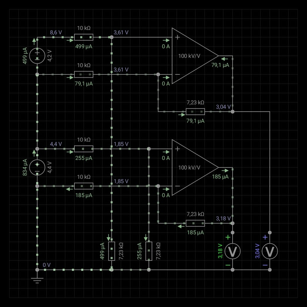
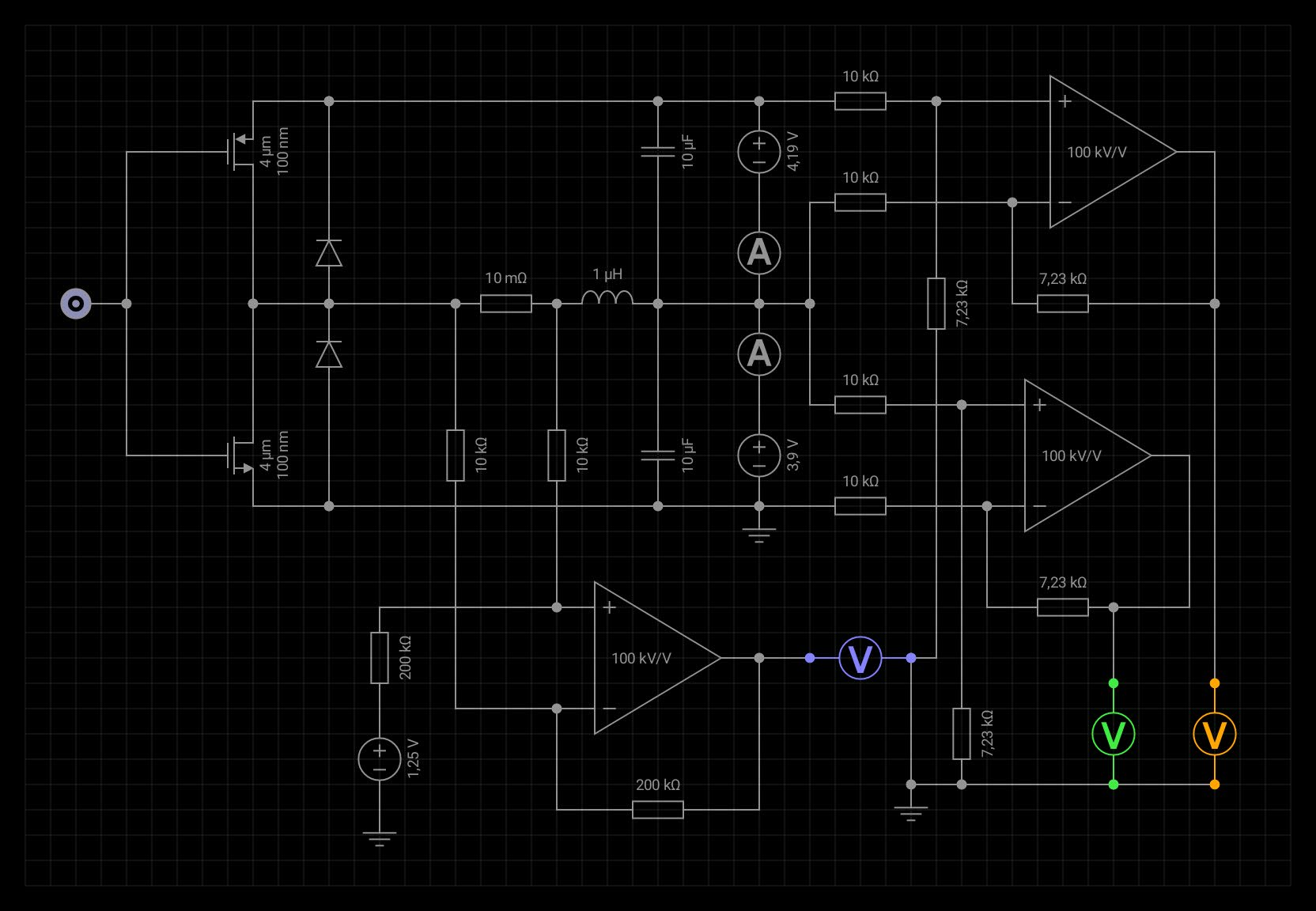
@G33RT @willy I’m working on a new idea/prototype without the ETA3000 but using an Synk buck covnerter instead. with a PWM DAC feedback using the uC. (this is a quite rushed process I have to order some other important boards so I create a single order for all the components, etc.)
It is based around this concept:
@G33RT Thanks fot the NXP document, I had missed that. We will see what we could do.
So far the goal is:
This one must have the following requirements:
** Due to HW limits balancing can start only above a precise voltage, thisis due to the opamp power rail limits
BTW naming suggestions are still open! I just renamed the pject due to a hurry but we could create a pool for that.
Another suggestion is to replace the output relay with a parallel mosfet circuit board of Heavy Duty Mosfets.
Due to high current I do not trust a relay because it can suffer from burnin contacts even it’s an Heavy Duty Relay.
Mosfets are a reliable choice to cut the power in case of emergency !!
Possible solution? How about a multi phase DC DC converter used to push pull energy from adjacent cells?
Lots of feedback is needed for CC/CV phases during balancing.
Anyway, we might have to go with a more strong STM32 chip. We need a higher PWM frequency than the one that an Atmega can make at 8mhz clock. (8mhz is due to the clk vs voltage supply)
Suggestion on how to read the currents and voltages are welcome. I think that a common voltage divider for the cel + 1 is not enough, we might need an diff op amp system. Also current measurements needs a diff op amp with a offset, (current can be bidirectional).
Any ideas are welcome!
My 2 cents:
Active Balancer doesn’t have to replace DIYBMS v4.*, better as add on option.
I can be misreading, to me it looks like the current idea is to improve, not add-on.
For power usage of the active balancer in small powerbank?
Yes that might be an issue.
Is it a problem not to target small powerbank??
Due nature of LiFePO4, it gets out of balance during charge and usage.
In passive state, voltages are almost equal.
During charge, I don’t give a sh!t about power usage, I care about Balance, and mostly that all cells get as close together to the +3.5v (3.65v) as possible.
Burning off charge is “high power usage”…
At usage, I also don’t care.
I suppose the active Balancer have start and stop voltage and rest 2.8-3.3.3v.
Between 2.8 and 3.3v balancing is “useless”, the few amps we are able to move don’t have real influence for total battery capacity.
Below 2.8, when a cell goes to 2.5 and the BMS stops the discharge, active Balance can “top up” this lower cell relative fast.
I have the 1A active Balancer from Ali.
For as far as I can see this is the cheapest ($75,-) active balancer available that really works.
It uses capacitors to store the energy from one cell to charge it to the other.
That makes the actual Balance 1A up or 1A down. (Or 1/2A continuous)
I am happy with this active balancer, as add-on.
Again, I can be mistaken, “all” people that use DIYBMS have minimal 2 controller boards.
(JLCPCB minimum order quantity is 5*, with 2* pre-solderd)
Maybe not all 2* wemos.
Just an idea, as the controller board is already there, something you don’t need to buy is the cheapest solution, yes? 
I’m just shooting ideas here.
If the controller board is “blank”, all space available for coding, can it be used for active balancing control?
The DIYBMS can do standard 800mA dump load, per small PCB.
That’s already amazing, compared to 35mA for Daly BMS on 1 line at the time.
Why not combine strength, leave the DIYBMS as it is, as it is a strong product as it is, and provide active Balance as add on for the DIYBMS?
How to do this technically…
No idea, I’m not that educated for electronics.
As “more advanced end user” I do have Ideas what is useful.
After finishing DIYBMS v4.21 I won’t replace it when it works good.
(And I am confident it will)
Most users are happy they where able to finish all the steps a d get a working BMS.
For many it’s their first adruino project, or even soldering…
I like the Idea of active balancing, many users do.
I also like the years of experience of Stuart and the years that the DIYBMS is successful running with many users.
I once had combination of BMS and active balancer…
It worked great for 3 whole days.
Not ready for launch, the seller got 100% return in the first few months.
Apparently the baby sickness is solved.
Original those people build active Balancers and thought " let’s put in BMS"…
Their active Balancer is good, doing BMS is clearly different skill set!!
I won’t be using a new developed product again to protect my 1016Ah, 50 kWh LiFePO4 battery (+/- $5.500,-)
I do have enough faith in the stability of DIYBMS.
Adding active Balancer that is compatible with DIYBMS would be fantastic solution.
Money wise, up to $5,- per cell / parallel string is for me a good price.
Especially if it can do more then 2 cells at the same time!!
With active balance I no longer need to worry about top balance each 6 months, and can use my battery between 15-85% to have long life cycle.
To do top balance, I need to charge above 85%.
Like most end users, once all is set and configured, I just want to “forget” about it,and let it do its thing for the next 5 to 10 years.
Maybe make a poll for add-on or “advanced DIYBMS” ??
Thanks for reading and your time!
I am totally impressed with yours and Stuart skill set, and how you are able to communicate at the same level!
To have an active BMS balancer you have to know the voltages of the cells around the cell n.
This in practice it means having a BMS that monitor all the cells.
So why having 2 system? The protocol has been inplemented to be compatible with the DIY BMS one so you could mix at match DIYbms and the “acti” one. My original board have both active and passive balancer, only SW capability is the limit.
I think that I’ll keep this project for a long/idefinite hold. I’m facing some issues on designing a decent circuit for a complete DIY solution without having to use a specific chip. (ETA3000)
If I will have more time I will try to create some other simulations of the circuit. I’m not an EE, i just used to study electronic at school. Some issue I’m facing are quite hard to trace and I don’t know how to proceed.
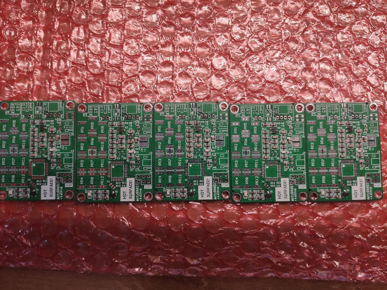
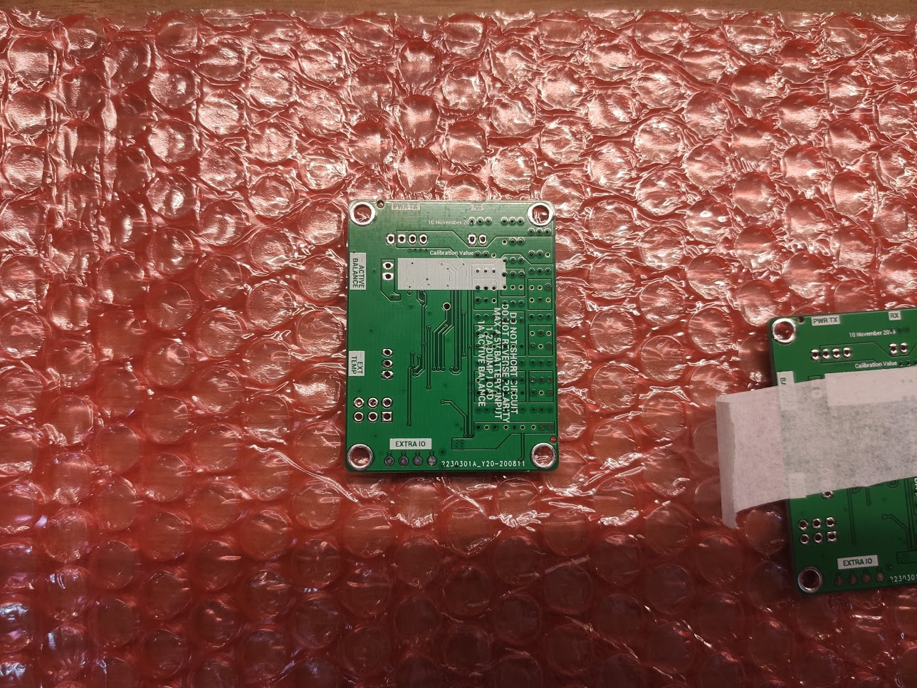
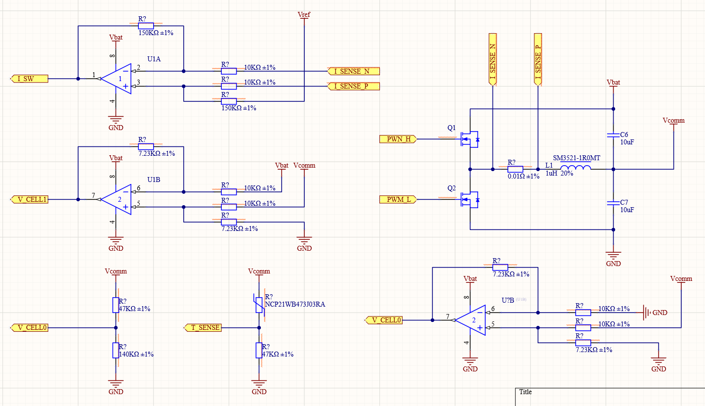
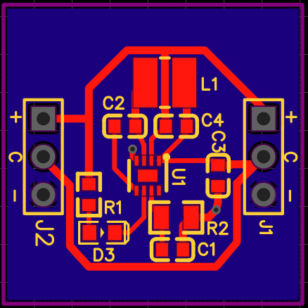
The current state of the actiBMS:
Thoose are the latest design infos I have for the complete DIY version:
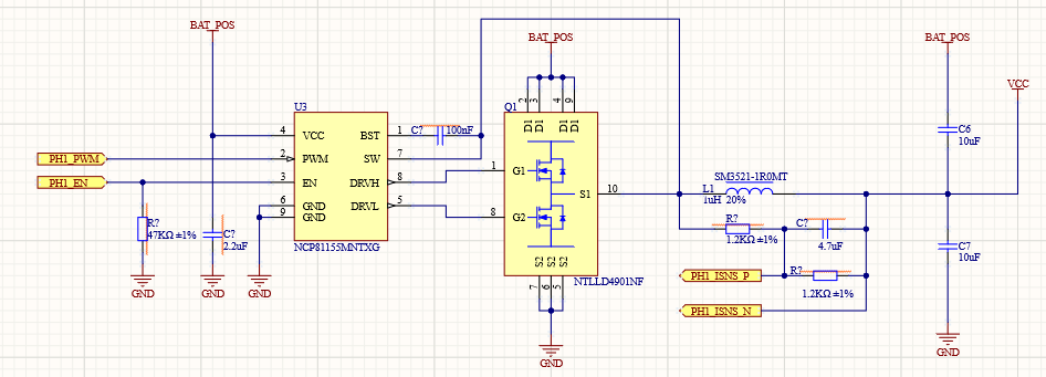
For a compact solution the pair NCP81155+NTLLD4901 with a STM32 is still a good solution, the issue is the op amps supply rail limit and the passive network current cosumption.
This is the corrent assembled board unfortunately due to a error in the schematic that I’ve missed I had to create a bodge wire.
Initial sw troubleshooting is ok:
Blink work fine, isp upload also. Fuses burned correctly. External resonator mostly ok.
probably the resonator need rework (looks like that the mcu sometimes get stuck if I touch and press the board)
Next step is check the addressable led and having a debug uart available.
Than I’ll have to wait the ETA chips. I hope they will come in a few weeks.
Hi all,
I was wondering if we could make te design simpler by adding an isolated i2c interface to following project.
Would be nice if we can get some reference values with an ADC Converter and the temperature
If we can make it addressable with jumper wires there will be no programming needed for the slave modules, only for the master module (to keep is simple 1 master per bank).
Any toughs on this?
Thanks!
That is a simple voltage follower circuit.
It works great but is not a proper active balance circuit with cc/cv phases.
If you want to use that just build a diybms and attached that module.
@hitech95, actually…
That isn’t a bad idea.
One of the great things about DIYBMS is its modular design.
And, as is, it’s great achievement from @stuart.
Sure, there is always room for improvement, improvement doesn’t need to be replacing.
Replace would be new product all together.
Add-on would make the installed DIYBMS around the globe better, instead of replaced.
I’m not looking forward to replace 48 cell modules just to add active balancing.
Buying external active balancer would be cheaper.
Not to mention the years of expertise that’s is lost when not using DIYBMS.
I do not have the skills to make add on based on the design of AfdhalAtiffTan.
Probably can solder it, not how to implement.
That is what I need you people!!!
I now use China 1A active balancer, and it is doing a good job.
I need to change my setup, and use 3* controller and 3* 16 cell modules.
Obviously, the active balancer can only be used for one group.
As already said if you have the diybms installed and you want also active balance just buy the china module and use it.
My design is the same china active balance in the same PCB of a diybms. It uses the same protocol nothing fancy.
And again to create a complete diy active balancing you need the same monitoring circuit of the diyBMS plus some other stuff. So you will end up with 2 boards that does the same things when you can simply unplug the diyBMS and attach the active balance one.
The diyBMS right now does not have additional IO pins and memory to control an expansion module.
This make no sense.
Hi,
The ETA300 looks like a very simple component to do active balancing,
I’ve build a 2 cell balancer that is yet to be tested and ordered, if you would like to
expand the current system you are using with an active one it might be a good idea
to place this one on top just like @hitech95 proposed.
The project is public on EasyEDA and feel free to comment.
https://easyeda.com/Gurk/activeballancer
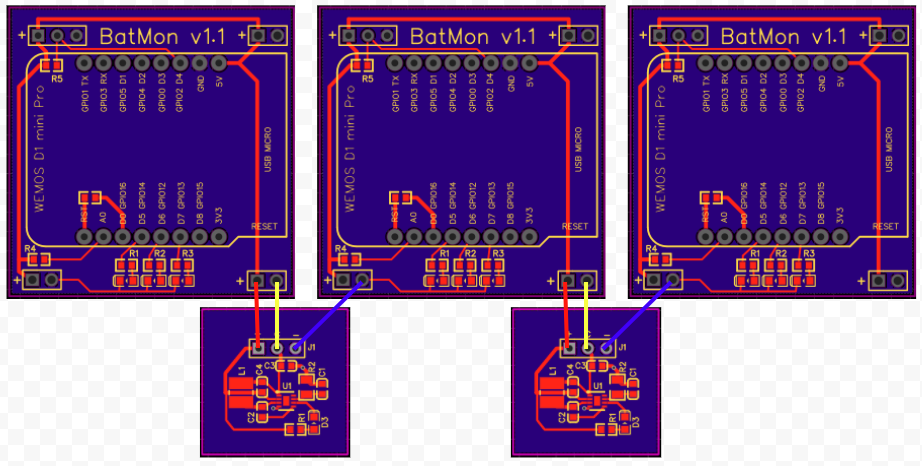
The plan is to build following module per cell and place a balance module between each cell.
https://easyeda.com/Gurk/celmon
Like so:
The Balancer is configured to be at 2A balance rate.
I will try to stack multiple balancers to go to 4/6/8 A for bigger packs.
Each cell monitoring board has a webserver running that returns a json object with the bank number
cell number, cell temperature and the voltage.
after each data request you send the Wemos to deepsleep.
The wemos will know when to wakeup because you give the read interval with the data request.
def request(ip, sleep):
req= requests.get('http://192.168.1.'+ str(ip) + '/data?sleep=' + str(sleep))Wauw.
Thank you all for keeping this thread alive!!
I have DIYBMS, and yes if it would already have been available, I would have build the actibms.V5
As it isn’t, I’m using version 4.21.
Throwing away something is always a bad idea if it is working just the way it is supposed to!!
I totally agree with all people who say that active balancer is useless product, totally unnecessary and waist of money.
If you always charge your LiFePO4 cells to +95%. Yes. Do not use!
You would spending your money on something that have totally no additional value and only costs some energy from your array.
If you don’t always want to charge to +95%…
You will increase the imbalance that natural occurs, not make it occur faster, it’s just not corrected every day.
That come with a price and a perk.
Perk 1000 cycles extra.
Price larger % imbalance.
What an active balancer will fix, being constantly active, correcting the naturally occurring imbalance.
The cheap China boards work fine, 1.2A, great.
Except that they won’t start until 0.2v difference between cells. !!!
It it would start at 0.05 or 0.1…
I would not even bother building, and just place then onto the cells.
Sadly, I have no idea how to change this threshold.
I wasn’t planning on ever letting the cells go out of balance that far. (0.2v) Ever.
Especially as I’m planning to keep the charge below 90% and above 10%.
I will look into the EasyEDA post.
Thanks for sharing!!
Hi Frank,
0.2volts is indeed not what you want.
@stuart, i read you wanted to ask JLBPCB to add the ETA3000 to the assambly line.
I also did and had a reply:
Yes,we have apply to add but there is no result now.
Do you mean Component C429740 & C429740 & C429740 & C523536 & C481061 & C393134 in
LCSC ?
Not sure if i can apply these.
The build with the ETA300 is based on an example to integrate the chip on the ETA datasheet.
And the scematics of @hitech95
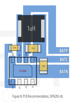
The result is this:
Based on the datasheet the balance voltage is quite accurate
I’ve started a new job so my free time went down a lot.
Right now I have a partially complete board, the ETA chip seems to be working fine.
Unfortunatly the ADC (I think its the code) is not working as it should and I have time to troubleshoot it.
Good luck on the new job!
I had a response of JLBPCB that the Inductor L1 of 1uF is to big for the print.
I don’t have the knowledge of calculating the values.
@hitech95 What component did you use?