Hi,
inspired by the new v4,I have decided to start working on a possible V5.
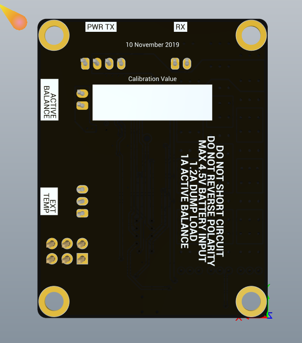
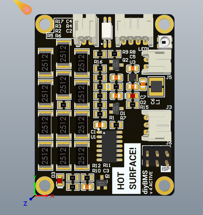
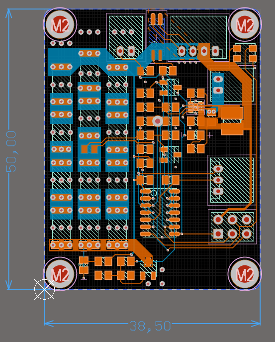
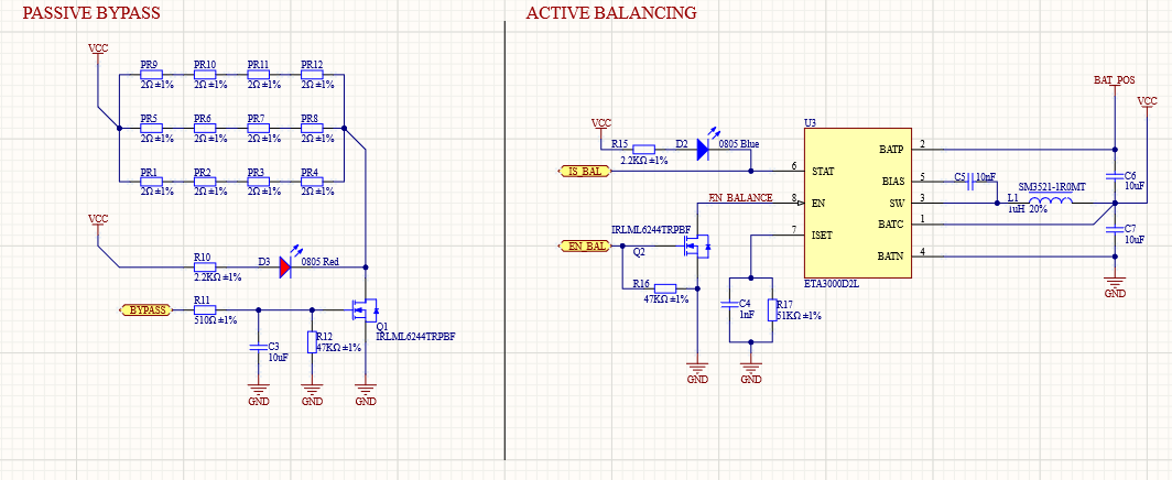
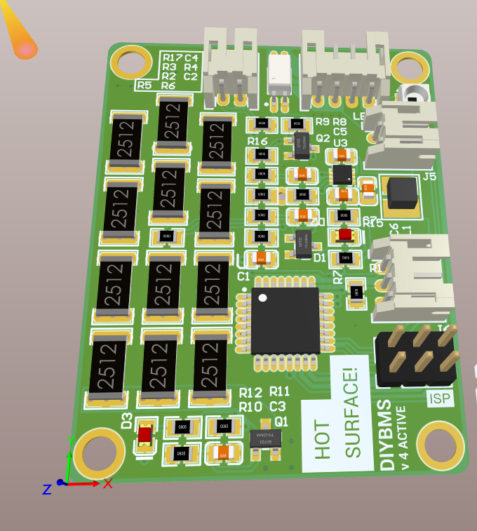
I have re-created the PCB to add Active Balancing using the Inductive process.
I have decided to use the ETA3000 chip, but it would have been quite cool to directly use the uC to handle the buck/boost circuit. (Unfortunetly the ATTiny don’t have enough RAM and IO to do also that. I had a demo/draft done by a ATMega, but in such case there are a lot of other issues/limitations. So a proper dedicated chip is easier to handle)
My board uses mostly all parts available at JLCPCB SMT assemply line, so the board could also be assembled directly during PCB manufacturing. Unfortunately the uC, the reference and the JST connectors must be soldered separately!
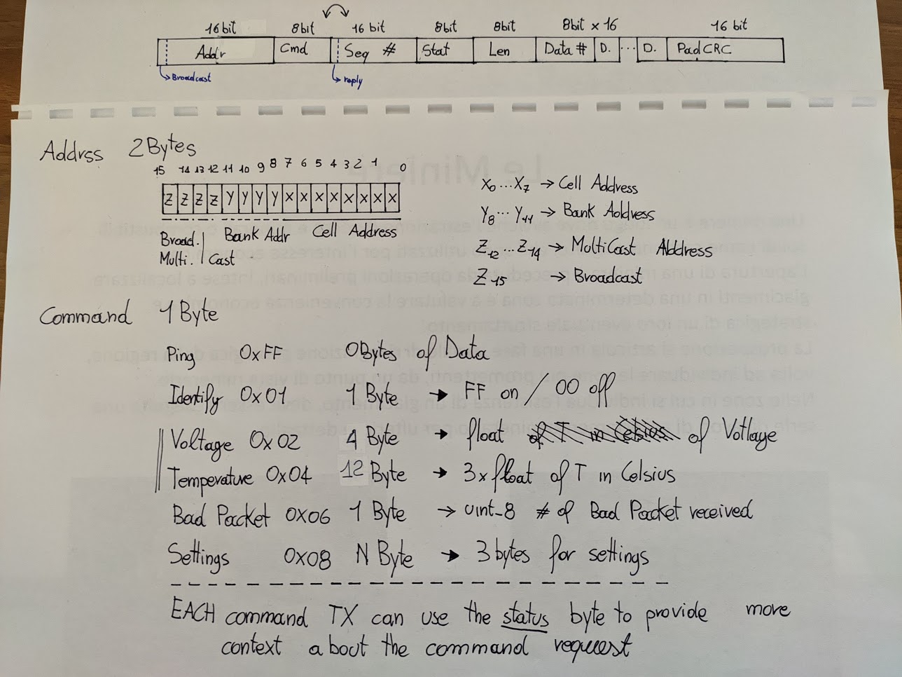
Anyway, I’m completely rewriting the software on the CellModule, I have unfortunately broken the v4 Protocol due to the fact that that I use a 16bit address, and I have made a lot of other changes. (This should also allow more that 16 modules in the chain/on the same bank)
My initial firmware idea was to use a Scheduler to handle all the tasks, but the low SRAM on the ATTiny doesn’t allow it. I was looking for an alternative parts with more SRAM but at that point a ATMega328p would be cheaper.
I have uploaded the sources of both the PCB and the firmware.
Please keep in mind that this is a Work in Progress project and things could change!
Unfortunately I’m an Altium guy so the project has been created with it.
Just to keep things clean on the forum, can you create a new topic with these posts in so we don’t confuse the readers. Don’t forget to publish your GITHUB source code branch as well.
The modder have splitted the post into another thread (@Robert.Wall Thanks!)
It started as a weekend project just to learn something new. Then I bought some 18650 cells and started to tinkering with them. I have seen that a lot of people was asking for an active charge version to I started to think how it could be done. At the same time Youtube suggested a video from Julian Ilett and I have discovered the ETA3000 chip!
@stuart
I have created an oganization for the diyBMS and I have sent you a request to be a member.
I’ll upload all the stuff I have about this new project as required by the license
If you have some ideas, thoose are welcome.
I have sent an email to LCSC to ask them if they can source the ETA3000 its a china brand type so souring it from EU/US is hard. Let’s hope they will stock them otherwise the project is at an dead end!
My roadmap:
Publish all the project files that I have to GitHub: Some are already there diybms · GitHub
Complete the Cell Module Firmware, test it on a ATMEGA. (I have implemented a “proper” HAL so porting between MCUs is easier)
Order the PCBs & Components to test out the final board, find bugs of FW.
Start the development of the Controller FW. And/Or Hardware. I think that the controller is fine, for our needs!
Actually not, but the Active Charger have a threshold of 100mV.
My idea was to use it while reaching a threshold value and then use the passive balancing to fine tune the value.
I have also adde you as owner of the organization!
Hi I’m new here. I has been following diybms since one month ago. I just see through the datasheet of eta3000. The balancing threshold between battery is 30mV and The 100mV different is to trigger the active balancing. And one thing I notice is if there are 3 cell, it could be 4.10V, 4.07V and 4.04V in the worst case scenario. But during charging, if the last cell is lowest in voltage, is it easier to charge? And become all quite balance?
Actually not, if the differnce between adiacent cells is lower than 100mV the balance process don’t start.
So let’s say that:
Cell 1 @4.18V
Cell 2 @4.04V
Cell 3 @3.95V
In this case cell 1 and 2 are balancing. Cell 3 & 4 are not.
At the end of the process the AVG voltage (cell 1 & 2) would be for example at 4.1V, this would trigger the balance process between cell 2 & 3.
Now lets say that the average cell voltage after the cell 1 & 2 is 4.02V the difference between cell 1/2 & cell 3 is 70mV which is greater than the “advertised” as 30mV end of balance voltage.
The ETA have two threshold values (AKA Hysteresis). For this reson I have left the passive balancer in the board. In this way we can TOP balance the pack with a more precise control!
I’m not a battery expert but as far I know this depends on the cell itself (like of the cell capacity, internal parassite resistor) and has not a lot to do with the voltage itself. The cell are in series so they get the same current across them.
I’m considering to switch to a ATmega168p (its also pin compatible to a 328p in case), According to JLCPCB/LCSC it’s cheaper than the AtTiny841 and have more Flash and RAM.
In fact the code is quite at flash limit. (I’m implementing a few more features and I’m running out of space. I only have a couple of bytes free and I still don’t manage the LED and I don’t read the state of the Active charger.
@stuart You have made a crazy job with that code! The Steinhart filter uses a lot of flash! In my test case it jumps from 65% to 99& of flash usage!
Think there’s a comment in the code about getting rid of the floating point maths. To be fair, you could push that calculation back to the esp module to do
I’m actually only using uint16_t around my code but the measurement/compensation is a float on that library. And for some “odd” reson takes half the memory!
The problem of moving it to the ESP is that we have still have to know the temperature for bypass, unless we use a worst/lighter aproximation.
Small update:
AVR LIB in the arduino platform is broken with the 328PB, so I have to revert to a 168PB/168P/328P.
This means that I don’t have USART Start of frame IRQs.
So I’m opening a poll to figure out what you prefere:
I prefer to pay 2 cents more that the ATTiny but more current consumption. (POWER_MODE_IDLE)
I prefer to pay 30 cents more that the ATTiny and have the 168PB that can be completly turned off. (SLEEP_MODE_PWR_DOWN)
0voters
I’m also implementing OneWire on the ICSP connector for another thermal sensor ore different device!
I have started the testing of the code main loop, tomorrow I’ll test the packet handler with the new protocol.
I’m also creating a wrapper for the old data protocol, I’ll se later how to do that properly. (I don’t use float, so I have to convert them.)
Ref the 18650 builds. Builders, don’t underestimate the value of capacity checking individual cells, labeling and then sorting to the final pack. “Average Joe” has a video to explain.
I have just started collecting my 18650’s to build a powerwall, now coming for and RC background I understand the importance of keeping your cells balanced, and the diyBMS project really interests me. I also feel the value of being able to monitor your cells via web or mobile with some sort of alerting is awesome.
So can someone thier direct me to the details or explain here the features of this project
Things like what’s the balancing current, can this bms balance a bank where the cell packs have 80-100 18650’s in each cell pack, what is passive balance or active charge
I know that the emonpi can do this, but it would be good to be able to add a shunt and monitor the discharge and charge current of the bank, have the option to add multiple temp sensors to each cell pack especially if the packs contain a 100 individual cells you really what to measure groups of 20 batteries, also push alerts to something like push bullet which can alert you.to a temp problem or major voltage descrepancy.
I do understand there are limitations to the size of the code and things like that, but if you.look at the Batrium Watchmon you guys are so close to providing a very similar product at a fraction of the price
The cell modules balance current is up to 850mA - although this drops if the modules exceed a temperature limit.
They have been used on large battery packs so 80-100 cells shouldn’t be a problem.
DIYBMS is a passive balance system - it “burns” energy to balance cells through heat and reduce the voltage on a cell. The BMS does top-balancing so balances whilst charging and tries to prevent cells going over a certain voltage.
Active balancers move energy from cell to cell to balance - this sounds ideal but is difficult to achieve in practise. Normally well designed battery cells which are well matched shouldn’t require balancing very often.