Accuracy of existing CT clamps since adding PV install - do I need an Emon solution?

Hi all,

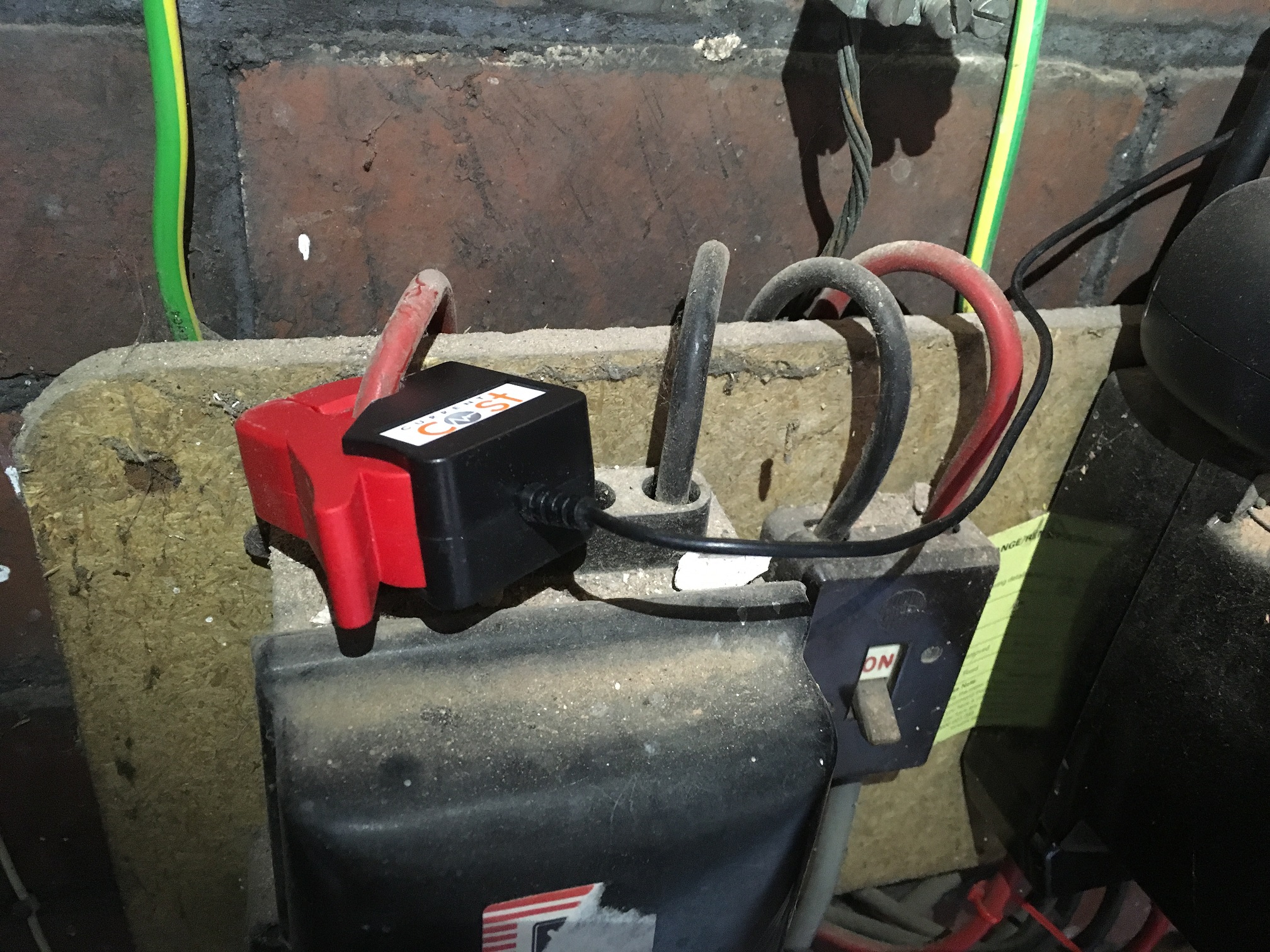
For the past few months i’ve been monitoring my household electrical usage via a Current Cost Envir CT clamp system connected to a Raspberry Pi running measureit (lalelunet / measureit · GitLab) and squirting the result up to PVoutput. The clamp was hooked close to my meter like this. So one of those old things the energy companies handed out years ago. But this one has rj45 and a serial connection, hence the connection to the Pi.

I’m in the UK by the way.

Here’s a pre PV install day… I think it was pretty accurate or at least in the ballpark for the most part.

https://pvoutput.org/intraday.jsp?id=66193&sid=58867&dt=20180814

But last week I had PV installed and since then the clamp readings have all gone to-cock. Its like the PV generation figures are interfering with the consumption figures. But worse than that, I don’t think it can be as simple as total - generation = consumption or anything like that. The maths never work out.

Even when out of the house and knowing the house is only using 250w, the consumption clamp still shows crazy high readings that flow in line with solar generation totals. I know my PV generation is right as that is coming from the Solar Edge API. I do have a clamp on the PV wire, but currently not using it to send to PVO. I’ve checked it though at that seems accurate under load… no sure accurate when not generating though as it shows 200w!!!

Here’s today.
https://pvoutput.org/intraday.jsp?id=66193&sid=58867&dt=20181006

All I want to do is monitor actual household consumption. How hard can it be? :slight_smile:

So this leads me to believe that the CT clamps i’m using are no good for when there is both in and out down the same wires/circuits. I’m no electrician so please forgive any ignorance. The way I that PV has been installed is that its come into a spare spur/breaker on the main consumer unit, so in essence the consumer unit and my system is now flooded with electricity from both directions; in (from PV) and out (from home usage) and the CT clamps have no idea what’s going on.

So if my Current Cost clamps are no good, will ones attached to an Emon solution be better? Could I monitor household consumption easily? And ideally without needing to get a sparky involved and £££ that could bring. The ‘learn’ section talks about adding PSU to the Clamps to give reference to the monitoring.

If an Emon based solution will work then what’s the cheapest and simplest way of doing it?
I have a spare Raspberry Pi knocking about if that can help? But i’m no soldering whizz, so things would have to be straightforward. Would I need 3 clamps/PSU and one Emon base unit?
Or if I wanted to monitor consumption and PV generation, would I need 6 clamps/PSU? I’m afraid i’m a bit confused by it all, sorry. :frowning:

Obviously, if there is a way to get the CurrentCost / measureit / Pi solution to squirt the correct figures to PVoutput that would be my preference as I already have the hardware etc and money has been invested.

Any help or pointers would be very much appreciated. If you need more info or photos etc please ask.

Thank you.

My initial guess, supported by “consumption clamp still shows crazy high readings that flow in line with solar generation totals” is “one of those old things the energy companies handed out years ago” doesn’t know the direction of power flow, and it’s only measuring the scalar value of current. (And incidentally, a clamp is something carpenters use to hold a piece of wood down.)

“The ‘learn’ section talks about adding PSU to the Clamps to give reference to the monitoring.” is exactly what you are missing. By relating the instantaneous voltage to the instantaneous current (and by “instantaneous”, I mean at sub-millisecond timescales) we can tell the direction of power flow.

You’ve clearly got a single phase standard UK supply, so an emonPi would do the job for you.
I don’t know anything about CurrentCost, measureit and PVoutput, so I can’t help you there.

You can buy the emonPi as a PCB only (the “emon” - energy monitor - part) and you can buy the case and display separately, and assemble those with your RPi. (I’m reasonably sure this is correct and there’s no soldering involved, the Shop will confirm.) You’d also need an SD card (or download emonCMS onto yours), two c.t’s and an a.c. adapter (which is NOT a power supply, it only provides a voltage reference for the ‘emon’ to measure the mains voltage). Presumably you do have a 5 V RPi power supply spare, which you’ll need to power the RPi.

This looks to be the cheapest, unless you want to expand at some future date and measure individual circuits.
The simplest (around £30 more) is a fully assembled and tested emonPi.

1 Like

To add to Robert’s answer, in addition to the usual issues arising from a lack of AC signal (not PSU) such as nor knowing the direction of flow, power factor and of course the voltage amplitude itself, adding a PV installation in to the mix will cause a previously acceptable apparent power based on a fixed 230 or 240v to be less accurate than usual as the line voltage will be higher during active generation to “tip” the energy generated towards the grid. My line voltage can be 10v higher when generating.

I would also suggest, as an alternative to Robert’s suggestion of an emonPi, an emonTx as a potentially cheaper option. The bare emontx is cheaper than the bare emonpi (and double the CT channels, whether or not you use them) and the addition of a case is half as much for the emontx as the emonpi. (CTs and AC adapters are the same for either option). There is the need for a cheap usb to serial adapter or some link wires to connect the emonTx to either the Pi’s USB or GPIO serial port and the emonTx case will not hold your Pi either, but depending on your application, it’s a viable option, both routes have pros and cons.

1 Like

Just some more information on CurrentCost Envi-R for the others (it was what I had before I switched to OEM), it is actually a two part system with a wireless transmitter and indoor display console. So the CT is connected to a “transmitter box” in the meter box (running off 3 “D” cells) with a base station inside the house which has the display and the serial connector for getting data off the display, in the same way an emonTx would talk to an emonBase.

So if @Zarch wanted to replace the Envi-R with the closest OpenEnergyMonitor equivalent, it would be an EmonTx in the meter box and an EmonBase plugged into his Pi (assuming he’s prepared to plug a “shield” onto his Pi instead of using the USB serial port). If a physical display is also required, then something else would be needed to fill that gap.

1 Like

And am I right that those systems work on VA = measured current x nominal voltage (or sometimes the display unit’s mains voltage), so can never determine the direction of power flow? That’s my understanding of many of these commercial offerings - particularly those that pre-date the widespread availability and take-up of PV systems.

1 Like

They certainly do, but you can adjust the V in steps of 10V to “calibrate” your nominal voltage. :slight_smile:

1 Like

Thanks for the replies, much appreciated.

AC Adaptor - Not a PSU… noted! :wink:

So it sounds like I could replace my CT clamp in the photo for my consumption and replace the CT clamp attached (but not currently used) on the cable coming from the inverter into the consumer unit (fuseboard).

And all my troubles would be over and I’d instantly get true consumption and generation?

Just to note and for further background, the consumer unit (fuseboard), electricity meter and PV inverter are all in the same location. I can also source an ethernet cable in there if required. So everything is almost next to each other, or least within a metre of so.

I’m not sure I need any screens or physical displays on the data collector. The location where everything is located is out of sight really and I could hopefully remotely configure or ssh?

Thinking ahead, if I was to get a battery at some stage in the future, which would the best purchase? EmonPi or TX? Do PV batteries connect via API? or via another clamp?

If I still wanted to upload to PVoutput, it looks like NodeRed is the solution and that runs on the same EmonPi? So maybe the Pi is the way to go?

mmmm, decisions decisions.

Looks like EmonPi (PCB Only - No Enclosure, Raspberry Pi or Pre-Built SD Card), 2 clamps, 1 AC adaptor is £96.

I have a PSU, a spare Pi and some SD cards I can use.

I’m happy to run without a case, i’m sure I can find something suitable. Does the PCB only selection in the shop come with the screen? I can’t see it mentioned nor see it available to buy as a separate item. Plus, do you actually need the screen, especially if running headless?

Thanks for the help so far.

Yes. But a word of warning: DON’T put c.t’s on cables without a load on the other end. OK, the ones we supply through the shop are supposed to have a protection diode in there to prevent a dangerous voltage appearing on the c.t’s secondary winding, but it’s best not to rely on that. If you do it with a larger c.t. that doesn’t have the protection, you can get very high votlages that will destroy the c.t. Remember it is a current source, so it will try to generate whatever voltage is necessary to drive the current it wants to into its burden - and if there isn’t one, it might flash over.

Hopefully yes, that’s the plan. You’d certainly get the nett grid power and hence energy (with the sign indicating direction) and similarly for the P.V, so the sum would be your house consumption (all within the accuracy of measurement, naturally). But there’s a bit of a learning curve to get the most out of your system.

EmonBase & emonPi:
An emonBase is essentially a radio receiver to take radio transmissions from an emonTx (or more than one, or one or more emonTHs, and pass the data into the RPi. An emonPi does that, it also has a 2 current and 1 voltage analogue input to measure 2 powers, and a simple 2-line LCD display. Both run emonCMS etc, and if your Pi has WiFi or Ethernet cable into your LAN, you can view the output on a web browser. There’s also some calibration available via the browser if necessary.

If you’re going to have a battery, it might well have a direct d.c. connection to your P.V. array, and we can’t offer an off-the-shelf way to monitor the d.c. link. C.T’s don’t work on d.c., and the emonPi & emonTx have only c.t. inputs.

It’s useful on the initial set-up, other than that, I find I rarely look at it.

I’m moving towards thinking that Paul’s suggestion of an emonTx with a direct serial connection to your RPi (not even with an RFM2Pi module to make it an emonPi) would be the better solution for you.

But the a.c. adapter can function as a power supply for the emonTx (just to add a bit more confusion :grin:)

1 Like