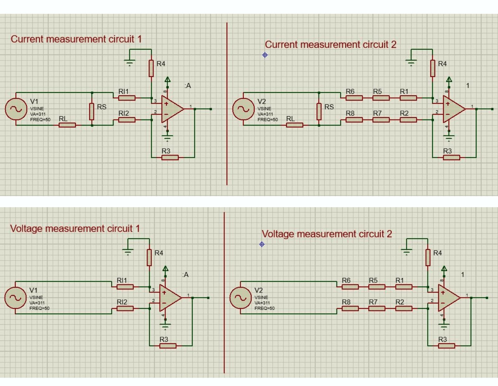
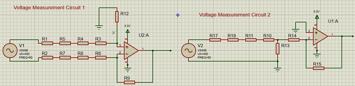
I am trying to finalize the AC voltage and current measurement circuit using a differential amplifier. I have designed two circuits for each. In the high side current measurement circuit 2 and voltage measurement circuit 2, I have connected multiple resistors in series to the inputs of the op-amp. However, in the high side current measurement circuit 1 and voltage measurement circuit 1, I have connected a single resistor to the inputs of the op-amp. I am planning to use 0603 package resistors. As I know that op-amps have very high input impedance, I used a single input resistor in circuit 1. I am confused about which circuit to follow for voltage and current measurement, respectively.
What is the voltage source you show as V1 or V2?
This implies you are making a direct connection to the mains electricity supply. I sense that you are inexperienced in matters of electrical safety and for both I would most strongly advise you to use an isolating transformer to give you complete isolation from the mains supply. There is always an element of danger, but have you considered what happens if the neutral wire breaks outside of your house? If it does, everything that’s on the drawing and anything connected to it becomes live at the full mains voltage, putting you is danger and anything connected at risk of damage.
I suggest you should use a voltage-output current transformer for the current measurement, as we do in the emonTx4; and for the voltage measurement you can follow exactly the circuit of the emonVs combined with the voltage input of the emonTx4. In each case, you have your op-amp where the input to the ADC is shown on our drawings.
The reasons for using multiple resistors in series are two: to reduce the voltage across each resistor, and to provide a degree of protection should one fail to a short circuit. In the case of the current transformer with a 0.333 V rms output, this becomes irrelevant because your op.amp will handle the 1 V peak-peak voltage directly. This is also the case for the ZMPT101B in the emonVs, because this too is actually a current transformer with a burden (the 75 Ω resistor).
Note that you are not completely safe even when you copy the circuit of the emonVs - everything on the mains side of the ZMPT101B and the transformer primary winding itself is live to the mains, so you must guard against accidental contact, and if you are designing a p.c.b, ensure you comply with the rules for separation between the mains tracks and the low voltage side.
Hi there, V1 is 220Vac and V2 is 3.3Vdc. I can’t use CT and PT as these are costly solutions.
I have warned you about the safety implications of NOT using isolating transformers. I cannot stop you from using a direct galvanic connection, but don’t blame me or OEM if you or someone else is hurt or your other equipment is damaged as a result of ignoring my advice.
If you proceed with the circuits you have drawn, both voltage and current must be “circuit 2” and the series resistors must limit the current, should the high voltage end of either the inverting or the non-inverting input be live to the full mains voltage, to no more than a few milliamperes (1 mA is the limit allowed for medical equipment). This implies R1 + R5 + R6 > 250 kΩ and equally R2 + R7 + R8 > 250 kΩ. These values should reduce the possibility that an electric shock is immediately fatal, should there be a system fault of the sort I described above and a person touches any part of the circuit or connected equipment and ground at the same time.
You must check the voltage rating of the resistors, and the actual ‘worst-case’ voltage across each should be no more than 50% of the rated voltage. Most ‘0603’ resistors have an absolute maximum voltage rating of around 50 V, so you would need around 10 in series to be safe. Four ‘0805’ resistors (150 V or thereabouts DC or rms) would be a much more sensible choice.
Really? You have drawn it as 50 Hz a.c.
What do you think is the purpose of RS & RL? These are only adding to the attenuation provided by R1 - R8.
Robert,
I think this website may explain the design…
Alas, it doesn’t help when the O.P. puts cost ahead of safety for themselves and those around them.
Thanks @Robert.Wall for your suggestions, indeed safety should be the first consideration while working with lethal high voltage. If you open the multimeter, you will find out they’ve also used a similar circuit, sense resistor and voltage divider for both AC - DC voltage and current measurement.
I am designing a low-cost smart switch with an energy monitor and measurement readings will be sent wirelessly so there won’t be any physical contact.
My mistake in the previous comment, V1 and V2 are the same 220Vac and the dc power supply of OPAMP is 3.3Vdc which I believe is isolated from the high side by the very high impedance of OPAMP and input resistors.
RS is low-value shunt resistor for the current measurement and RL is the resistive load.
Yes, @Robert.Wall I have referred to that link as well.
For the AC voltage measurement, my senior recommended using a voltage divider and inverting opamp instead of using a differential opamp as in differential opamp we are directly feeding 220Vac to the inputs of the opamp. What would you recommend for the AC voltage measurement?
When I do that, I make very sure it is not connected to the mains supply. So your device, when it is finished, will have no galvanic connection to the outside world other than via it’s input connections. How are you going to develop and test it? There’s still a significant risk there.
I will be putting my PCB in a 3D printed PLA enclosure, so only the connector will be outside.