No you won’t.
His diagram is wrong - as the note says (and you’ve only got to look at it for a moment to see it’s wrong). It should be like this:
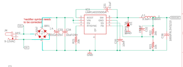
The diodes should ‘point’ upwards and the output is top (+ve) and bottom (-ve) and the a.c. feed is to the middle.
Now, you can connect the 12 V d.c. to GND (-ve) and +ve to the barrel socket, either centre pin or the sleeve or both in parallel. The LMR can accept up to 40 V input, there’s not much difference between feeding it 12 V d.c. and rectified and smoothed 9 V a.c., and it will be dissipating even less power than if you feed it 12 V a.c. - the voltage in that case on Vin is likely to be higher at around 16 V. And you don’t get a diode voltage drop between the two GNDs.