Hello, I borrowed a calibrated CT meter from work to check the accuracy of the emonpi and there seems to be an accuracy issue at low current. I am seeing 1A missing (lower) on the emonpi at 2A draw but at 10A draw there is no issue and shows the correct reading… what gives?
It’s probably the c.t. you’re using. If it’s the ‘standard’ YHDC SCT-013-000, the accuracy is quoted at ±3% from 10% to 120% of rated current. In other words, no accuracy is specified below 10 A.
Are you looking at rms current, or are you inferring it from voltage and real power?
The error if the real power calculation at low currents is largely phase error in the c.t. itself - if you look at the test report in ‘Learn’, you can see how the phase error increases at low currents. This loss of accuracy at low currents is inherent in all c.t’s, it’s just that if you pay about the same as your emonPi a single c.t, it will be good to a much lower percentage of rated current.
The amplitude of the secondary current is affected rather less, my measurements show it remaining linear to a much lower value.
OK, so I need a better CT sensor, is there anyone that is recommended as a replacement?
Another option would be to run 2 or more turns of the current-carrying conductor through the CT’s
window, then divide the result by the number of turns through the CT.
It’s not always possible to do that for a number of reasons, but it is one alternative.
It sounds as if you’re measuring a relatively low current value. i.e. low relative to the CT’s 100 Amp
maximum rating. If you use a CT with a smaller max rating, e.g. 50 or even 30 Amps, you won’t
see the issue you’re having to quite the same extent. The idea is to choose a CT with a max
rating as close to the value you want to measure, yet allow for some headroom.
e.g. if the maximum value of the measured current is 25 Amps, you’d use a 30 Amp CT.
There are these from RS Components, which are directly compatible (with a change of calibration of course):
UK c.t’s 25 A / 40 A / 50 A: https://uk.rs-online.com/web/p/current-transformers/7754909 or /7754903 or /7754912 Secondary 50 mA. (Ignore ±400 A Output, it’s wrong, the manufacturer’s data sheet: https://talema.com/wp-content/uploads/datasheets/AZ.pdf)
or
https://uk.rs-online.com/web/p/current-transformers/1243897 50A:50mA.
https://uk.rs-online.com/web/p/current-transformers/1243896 25A:50mA.
These are all ring-core, which are normally ‘better’, there’s no risk of an air gap to spoil the performance. The snag is, the circuit must be disconnected to install the c.t.; and you’ll need a 3.5 mm jack plug (mono or stereo wired tip and sleeve). Plus, there’s no over-voltage protection so the c.t. must never be disconnected from its burden while the circuit is energised.
OK, I’m going to have to calculate a changing scale up to 10A. Can only use non invasive clamps as disconnecting meter tails is out of the question. thanks anyway
Are you sure your numbers are correct - meter tails, 10 A maximum? This sounds unlikely to me, I’d normally expect at least double that, and in many cases double that again.
It may well pay you to carefully calibrate the Pi’s current input - particularly the phase calibration, because it’s the phase error that changes most at low currents, and it’s also the parameter that changes most from batch to batch. (The phase error is not specified at all by the manufacturer.) The default value is only our best estimate when a sample was tested. Instructions are in ‘Learn’ for the emonTx, the emonPi front end is to all intents identical. However, I’m not sure where the front end software is in terms of being able to calibrate via your browser, or whether you need to recompile the software and upload it each time you make an adjustment.
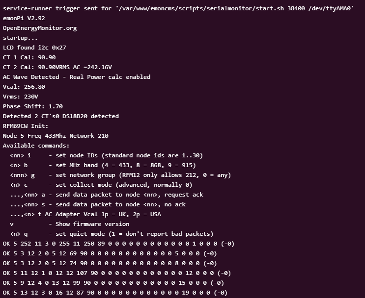
If you go to Setup → Admin → Serial Monitor and send the command ? you should see a list of commands for setting up and calibration. If it’s a long list that contains k<x> <yy.y> <zz.z>, then you can indeed calibrate via the browser. <yy.y> and <zz.z> are what you change instead of Ical and phase_shift. When you’re happy, s will save the changes to EEPROM.
(Hint: as long as you time sending your calibration commands between the data messages coming back, you don’t need to stop emonhub. It averages over the 10 s reporting period so you need to wait for the second reported value after a change to see the full effect of the change.)
Manual calibration would probably be the way to go instead of trying to manipulate feed output.
Is there a guide anywhere for this, I can’t see the options you mention, I’m using stable release tree only.
You don’t appear to have the front-end software that accepts the calibration commands. I don’t know why - I thought it was available in the current SD Card image.
And you’d be manipulating the Input, not the Feed (the Feed is the database).
Can you answer the question I asked earlier:
Do you have a programmer?
It might sound daunting, but I’ve found the easiest way to calibrate the emonPi Shield (the “emon” front end that does the power measurements) is to take the emonPi apart, separate the Shield from the Raspberry Pi and treat it exactly like an emonTx (but you will need to use the 5 V d.c. supply to power it (unlike the emonTx, which can get its power from the programmer). You’ll need to download the front end software and install the Arduino IDE in order to edit the files, compile and upload with the necessary changes to the calibration.
If you don’t want to take the emonPi apart, it’s said to be possible to edit the files inside the RPi, compile it on the Pi and upload from there. I’ve never tried to do that. The only other way I’ve done it, to how I’ve described, is by editing and compiling on a “proper” computer (laptop) and then sending the compiled file to the Pi and uploading remotely from there, using Remmina or similar tools. Taking the emonPi apart cuts out the last step.
The snag is, you’ll then need to be very careful and not allow the emonPi to do a full update, or everything you’ve just changed will be overwritten.
It is from RMS current and no, I don’t have the programmer. I’ve decided to leave the discrepancy for now as it doesn’t effect the pulse count which I use for meter readings.
On emonpi in Inputs you can setup a calculation that allow add, subtract, divide and multiply that can be used to calibrate any errors with a bit of maths you can lower the output to a lot closer to your reading
Yes, but that won’t - cannot - fix a linearity issue:
Anything done to “correct” the 2 A reading will either degrade the 10 A reading or readings somewhere else on the scale.