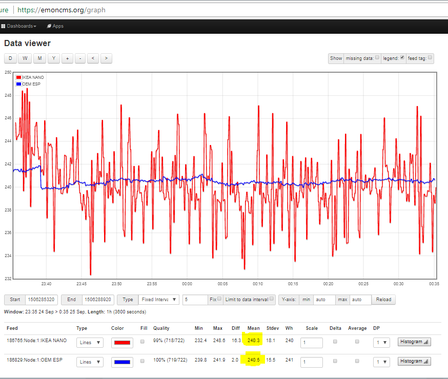
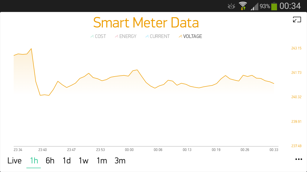
Fair comment but until I know otherwise I will say that Ikea is producing a true reflection of supply voltage. I am not an Electrical Engineer so I don’t know how it’s working but it’s following the daily 10V regular dip we see here.
When I have more time I will try to plot OEM v Ikea v Energy Monitor to back up my assessment.
You are fully entitled to do that, but the responsibility is yours, not mine, nor OEM’s, nor Megni’s, should someone else follow your example and find that they get poor results, which is the best case scenario, or damage their equipment or themselves, or cause any harm to themselves or others.
Here’s something to consider.
Lets assume your electronic transformer is indeed producing a high frequency switched “sine wave” approximation of the mains voltage as per Figure 3 in the link sent by Robert above:
The way emonTX works is to sample the instantaneous voltage and current multiple times per AC “cycle” (each AC cycle happens 60 times per second for 60 Hz AC). if the sample is taken at the exact point in time when the electronic transformer is oscillating through 0V (as an example), the “real power” it calculates will be 0W, regardless of the current flowing. This will cause your “real” power" measurement to be even less accurate than calculating “apparent power” (ie. not using a voltage source).
You are concentrating on the RMS voltage, which by its very nature is an average and is only a very small part of the equation here.
I am now slowly starting to understand the different elements that make up the “emon” system.
And I’m sure you are right that it would be almost as accurate just to say supply voltage is “fixed” at 240V rather than rely on the Ikea adaptor for this “variable”.
I have watched the linear PS and SMPS videos, twice, but to be honest I can’t say it made things much clearer.
Does anyone know of a basic video that might make all this apparent / real power and instantaneous current / voltage clearer in my mind.
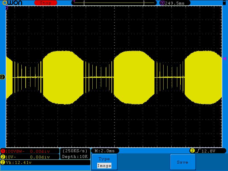
Indeed! I third that. I’m not surprised George sees a good Vrms correlation between the input and output voltages on these things. As far as I can tell, there’s no real regulation. The amplitude of the mains/primary swing seems to directly impact the amplitude of the secondary/output swing. For kicks I plugged an Osram ET-Redback into a variac and put a 20W bulb on its output. The variac knob appeared to be a very effective (if impractical) dimmer.
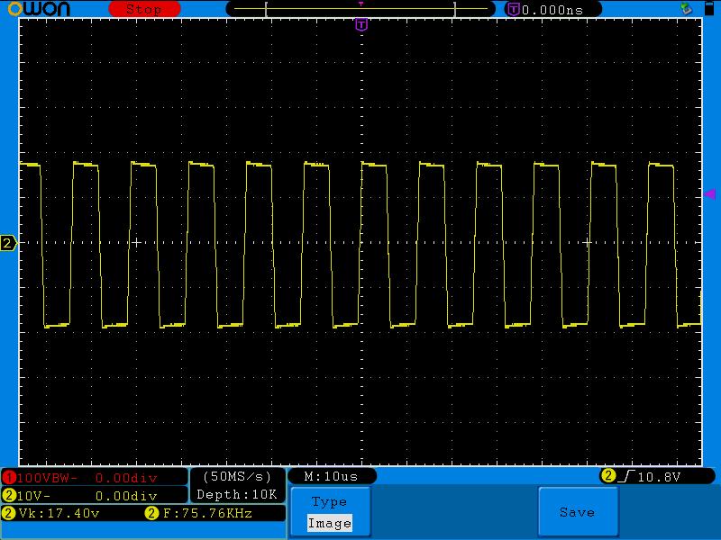
I then hooked the output of the ET to my scope (still driving the 20W incandescent bulb). You can see those big yellow blobs occurring every half line cycle (10 msecs) and when you zoom in on them, you can see a square wave at about 75kHz.
George, at best you might be able to deduce Vrms of the line voltage from the output, but as Robert and Greebo have pointed out, if you want to measure real power, you need the voltage signal to be an accurate scaled down version of the AC mains voltage signal, and it’s clearly a million miles from that.
If you’re only interested in measuring apparent power, then the mains voltage you deduce from the ET output might be more accurate than just a hardcoded 240V.
Have another read of this Learn page:
https://learn.openenergymonitor.org/electricity-monitoring/ac-power-theory/introduction
Looking at diagram 1 and 2, imagine those Red lines NOT being the nice smooth sine waves in the picture, but instead being a “chopped up” sine wave (switched mode) as per dBC’s post above, where the average just looks like the sine wave. EmonTX is sampling the values of voltage and current at discrete intervals and you can’t know if the voltage at that interval is the “correct” value (if it was a smooth sine wave), or not, because it is NOT a nice smooth sine wave but in fact a chopped up approximation of one.
Thanks @Robert.Wall @Greebo and @dBC it’s starting to make more sense.
In my defence, as per the title thread, I set out to see if I could safely “measure” AC voltage from an adaptor I already owned. The answer appears to be yes but this “measure” coupled with CT readings will not provide accurate power usage figures. Which ultimately is the intended goal and the OEM adaptor is the best known system currently available, coupled with the CT’s.
I’m tempted to buy additional OEM adaptors but I think I will wait until the CT’s arrive and until I understand a lot more of the theory behind all this.
In our defence, you never actually explained what you wanted to “measure”. ![]()
You are posting to the Open Energy Monitor forums, where “measure” regarding AC voltage specifically means seeing as close as possible to the true (but scaled down) AC waveform, nothing to do with the Vrms value (although it is included in the data sent to emoncms).
It is most important to realise that the Vrms value is not used inside the emonTX when calculating the power consumption. This line from the Learn page I linked to above is most critical (my emphasis):
This is why you need accurate representations of both the voltage and current waveforms
In the Getting Started section ![]()
What purpose does this serve?
Some people like to know… If you’re calculating it, why not record it?
Maybe its interesting to see how your supply voltage varies for a certain use case?
One further question:
Shop for OEM adaptor states (emphasis is mine):
“Used to give AC voltage sample to measure the AC RMS voltage which in turn can be used to calculate real power, power factor, frequency and detect power flow direction.”
Is the description a little misleading for beginners like me?
Perhaps better wording could be …to measure the AC voltage waveform… but that may be even more confusing to beginners, most of whom will have at least heard of “RMS voltage” even if they don’t know what it means 
It doesn’t actually say that the adapter measures the rms voltage, only that the adapter is used to give a voltage sample, and it is the voltage sample that is used to obtain a measure of the rms value. The same sample could be used to measure the peak, the peak-peak, the average (should be zero), the rectified average and the various factors that we use to relate those terms. And that’s without mentioning the relationship between current and voltage, which is where real, imaginary and apparent power and their relationships come in.
For those who are at the bottom of the learning curve, even @Greebo’s version could be shortened to “to measure the AC voltage”.
The real problem with the shop wording is, the rms voltage is not used to calculate real power, nor the direction of power flow (but the waveform at any instant is).
@glyn.hudson
That was my real point, despite my emphasis on RMS. As a beginner I looked through the docs and the shop offerings and then asked myself do I already have one of these “very special adaptors”. From the very basic, read wrong, description in the shop the answer was yes. Which turns out to be a resounding no and I’m pleased I bought the OEM adaptor.
I’ve already sent a PM to @Gwil about this.