AC - AC Adapter and Arduino for Measuring AC Voltage

Could someone please indicate what the significance is of a 9V AC - AC adapter other than it’s low voltage and therefore relatively safe for numpties like me.

The only adaptor I have close to a 9V AC - AC is an Ikea transfomer for one of their small (20W) light fittings. The adaptor is marked up as Primary 220 - 240V ~ 50Hz and 0.1A with secondary of 11.5V ~ 10 to 20W.

At this stage I’m just looking to obtain AC voltage and will move on to current later so I worked through the “9V AC - AC adaptor” tutorial. I hacked the Arduino library and sketch just to provide voltage and it came out pretty much spot on except it was double the actual voltage. So a further hack to halve the values and the figures look ok.

Is this a pure fluke and it’s simply not possible to get the correct figures with the “Ikea” adaptor I have?

I only have 0.1 μF and 100 μF caps which are both 10 times too big / small compared with the 1 μF to 10 μF range recommended. I plumped for 0.1 μF as it’s says the cap size is not critical but open to suggestions. I have 5 off 100 μF so I guess I could get that down to 20 μF in series if it’s important until I pick up some 10 μF caps.
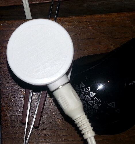
The AC adapter is a safer way to obtain the mains voltage without messing with 240v AC.

The one sold in the shop has been selected to provide the most accurate and cost effective method for reading this value, so randomly picking a similar transformer will give different values as you are seeing.

Thats not to say the unit you have is bad/worse, just that the components on the circuit all need to be designed to match and work together.

1 Like

Thanks @stuart but I was wondering what parameters I might need to change for the “Ikea” I have.
I worked through the calcs and checked that I would still have head room within the 0 - 5V ADC based on 11.5V rather than 9V but I’m sure there is more that I am missing.

You can use any isolating transformer you like, provided that it gives you greater than 1.6 V on no-load, and provided that you change the voltage divider resistors R1 & R2 accordingly. We use the nominal 9 V a.c. adapter because it is CE marked, readily available and safe.

If you got the numbers right, then you should have been close to the correct value. The first stumbling block is the transformer label. Small transformers like yours (and the a.c. adapter we use) give the rated voltage at full load. At anything less, the voltage is greater, sometimes by a considerable margin (our 9 V adapter gives 11.6 V ±3% on no-load for 240 V in). What you need to do is measure the voltage out of your transformer (and the voltage in) to determine the actual ratio to use in the maths.

I’m assuming what you have is just a transformer, and it’s not a d.c. power pack with a rectifier etc inside? That won’t work with the circuit in the tutorial.

Having got the voltage, if it’s less than about 11.5 V (which is roughly what the standard a.c. adapter gives you with no load), then you can use the voltage divider resistor values in that tutorial. If it’s greater, then you need to increase the value of R2, or reduce the value of R1, so that you get about 1.6 V a.c. across R1 at your maximum mains voltage (254 V if you’re in the UK). Then you can do the sums.

I don’t understand what you mean by this. There’s no need to “hack” anything. EmonLib should not need to be changed, all you needed to change was the number “234.26” in the line

emon1.voltage(2, 234.26, 1.7);

and add

Serial.println(supplyVoltage);

just before the end of loop( )

The capacitor value isn’t important. If you go below 1 μF, the mid-point won’t be steady and you will have inaccurate readings, there’s no point in going larger than 10 μF. If you put a 100 μF in, it will take ages to stabilise when you switch on.

1 Like

Now that’s interesting because with a 20W bulb as a load I get readings of around 6.5V to 8.5V but with no load I get nada.

Serial Monitor shows the following:

Apparent power: 24.77 W	 Supply voltage: 247.71 V
Apparent power: 22.76 W	 Supply voltage: 227.64 V
Apparent power: 24.32 W	 Supply voltage: 243.22 V
Apparent power: 23.82 W	 Supply voltage: 238.22 V
Apparent power: 23.29 W	 Supply voltage: 232.91 V
Apparent power: 23.26 W	 Supply voltage: 232.62 V
Apparent power: 23.84 W	 Supply voltage: 238.42 V
Apparent power: 23.64 W	 Supply voltage: 236.40 V
Apparent power: 24.44 W	 Supply voltage: 244.39 V
Apparent power: 24.30 W	 Supply voltage: 243.02 V
Apparent power: 23.32 W	 Supply voltage: 233.24 V
Apparent power: 23.26 W	 Supply voltage: 232.60 V
Apparent power: 23.75 W	 Supply voltage: 237.48 V
Apparent power: 24.30 W	 Supply voltage: 243.02 V
Apparent power: 24.28 W	 Supply voltage: 242.82 V
Apparent power: 22.99 W	 Supply voltage: 229.91 V
Apparent power: 23.49 W	 Supply voltage: 234.88 V
Apparent power: 23.61 W	 Supply voltage: 236.10 V
Apparent power: 24.93 W	 Supply voltage: 249.32 V
Apparent power: 23.06 W	 Supply voltage: 230.56 V
Apparent power: 22.91 W	 Supply voltage: 229.10 V
Apparent power: 22.93 W	 Supply voltage: 229.32 V
Apparent power: 24.33 W	 Supply voltage: 243.34 V
Apparent power: 24.57 W	 Supply voltage: 245.70 V
Apparent power: 23.61 W	 Supply voltage: 236.06 V
Apparent power: 23.75 W	 Supply voltage: 237.48 V
Apparent power: 24.66 W	 Supply voltage: 246.58 V

With the following hacked sketch:

// EmonVoltageV2.ino EmonLibrary examples openenergymonitor.org, Licence GNU GPL V3
// this doesn't require any library hacks

#include "EmonLib.h"             // Include Emon Library
EnergyMonitor emon1;             // Create an instance

void setup()
{  
  Serial.begin(115200);             // was 9600
  
  emon1.voltage(2, 240, 1.7);  // Voltage: input pin, calibration, phase_shift was 234.26
  //emon1.current(1, 111.1);   // Current: input pin, calibration.
}

void loop()
{
  emon1.calcVI(20,2000);         // Calculate all. No.of half wavelengths (crossings), time-out
  //emon1.serialprint();           // Print out all variables (realpower, apparent power, Vrms, Irms, power factor)
  
  //float realPower       = emon1.realPower;      //extract Real Power into variable
  //float apparentPower   = emon1.apparentPower;    //extract Apparent Power into variable
  float apparentPower   = (emon1.Vrms / 2) * 0.1;    // hack for apparentPower at fixed 0.1A
  Serial.print("Apparent power: ");
  Serial.print(apparentPower);
  Serial.print(" W\t Supply voltage: ");
  //float powerFActor     = emon1.powerFactor;    //extract Power Factor into Variable
  float supplyVoltage   = emon1.Vrms;             //extract Vrms into Variable
  Serial.print(supplyVoltage / 2);                // was just supplyVoltage
  Serial.println(" V");
  //float Irms            = emon1.Irms;           //extract Irms into Variable
  delay(2000);
}

Thanks for the details on caps. When you say it will take ages to stabilise at 100 μF are you able to be a little more precise?

Forget that line, it is total rubbish. As you are not measuring current, "apparent power is quite meaningless. You are misleading yourself by doing something like that. Add instead the line I told you to.

What are you reading the voltage with? Do you mean you read zero volts? If so, I don’t believe something you’ve told me. But I’m not sure what that is at the moment. I suspect you don’t have just a transformer. What exactly is the apparatus that the transformer came from? Can you give me a link to its web page? Or a photograph of the rating label?

Ikea don’t use labels it’s stamped into the adaptor and almost invisible under a magnifying glass and LED.
Let me see if I can find the lamp on Ikea’s website.

Yes zero volts with a DMM. I’ll treble check this asap.

@Robert.Wall my DMM only has 200 and 600V settings for AC. With no load, on the 200V setting the meter alternates between 0 and 0.1V. Does this mean it’s not suitable as it appears to be well short of the 1.6V zero load value?

No, I think - but I can’t confirm it - it means that your transformer isn’t giving you an a.c. output at all, but d.c. And when you load it with a lamp, you are measuring “ripple”. Do you have a suitable d.c. range on your meter, and what does that read? If it’s a true transformer, it should read zero. If it reads any substantial voltage, then it’s a power supply with more inside than just a transformer. And in that case, and it’s a sealed unit you cannot open up easily, it’s not suitable.

If you’re going to seriously experiment with this sort of gear, I think you should think about getting a more suitable DMM. There’s a page in ‘Learn’ that might help you.

About 1½ minutes to get within a couple of percent of the final voltage, if you’re using 470 kΩ bias resistors, although you’ll get stable readings before that.

Much better range on DC, up to 200mV, 2V, 20V, 200V and 600V, On DC with zero load it’s 1 to 3mV.

I would say it’s an AC supply as confirmed by the embossing by Ikea.

Image below but you’ll probably not be able to read it.

Yes I have the 470K bias pair, I’ll drop in the 100 μF and see what it comes up with.

You’re right, I can’t read it. You needed a very low angled light to give bright edges and to throw shadows.

What sort of a lamp is it, tungsten halogen filament?

@Robert.Wall spent ages stripping the lamp down to see what type of bulb it has. Ikea bulb made in China but the short reference number isn’t found on Google.

Basically it’s this svetnova.ru which I believe is halogen and they are normally AC.

Swapped out the 0.1 μF for the 100 μF and have removed my " / 2" hack from the sketch. Serial Monitor now shows the following (ignore apparent power).

Apparent power: 25.74 W	 Supply voltage: 257.37 V
Apparent power: 24.95 W	 Supply voltage: 249.48 V
Apparent power: 23.40 W	 Supply voltage: 234.01 V
Apparent power: 24.95 W	 Supply voltage: 249.51 V
Apparent power: 22.53 W	 Supply voltage: 225.26 V
Apparent power: 23.01 W	 Supply voltage: 230.15 V
Apparent power: 22.17 W	 Supply voltage: 221.70 V
Apparent power: 22.99 W	 Supply voltage: 229.92 V
Apparent power: 24.36 W	 Supply voltage: 243.61 V
Apparent power: 26.03 W	 Supply voltage: 260.32 V
Apparent power: 21.81 W	 Supply voltage: 218.10 V
Apparent power: 26.30 W	 Supply voltage: 263.02 V
Apparent power: 24.55 W	 Supply voltage: 245.53 V
Apparent power: 22.06 W	 Supply voltage: 220.64 V
Apparent power: 24.06 W	 Supply voltage: 240.61 V
Apparent power: 21.94 W	 Supply voltage: 219.44 V
Apparent power: 28.44 W	 Supply voltage: 284.43 V
Apparent power: 26.36 W	 Supply voltage: 263.62 V

So something like mains voltage. I used a low 212 value for calibration similar to the FP AD 3515 but only because it made the numbers look more reasonable.

Hmm…
I wonder whether, if you seriously need an accurate measurement of mains voltage, it’s time to invest in an a.c. adapter that’s known to work and for which we have calibration data?

But I wouldn’t expect it to be jumping around quite so much - 220 to 260. Either you have a very soft supply, or you had a particularly heavy load on the same ring main that was switching on and off.
If your transformer is 11.5 V on full load (which seems a reasonable assumption, but not necessarily correct) and the regulation is 25% (the same comment), then the no-load voltage will be 14.375 V. Assuming that is at 240 V, and with the 11:1 divider, the calibration constant will be 158. If the voltage is 11.5 V on no load, then the constant is 126.5. A constant of 212 means the transformer is giving you something like 19 V, and at that voltage, you should change R1 to a higher value (say 120 kΩ or 150 kΩ) so as not to ‘clip’ the waveform when the instantaneous voltage goes outside the power rail voltages.

If it helps with calibration the value going into the analogue port is almost exactly 2V (DC) and stable. When I connect up the meter it starts around 2.35V (DC) and gradually drops to the 2V. Is this the effect of the capacitor charging up? Or shouldn’t there be any DC values in the circuit if it’s the correct type of adaptor?

We don’t have any heavy loads on any ring mains.

We actually have an off the shelf smart meter and the supply voltage is pretty stable. Over the last 24 hours the minimum was 229.2V and the maximum was 243.7V. These values are 1 minute averages of the supply voltage so some of the readings could have been higher or lower than this range.

The standing (quiescent) d.c. level on the mid-point should be half the d.c. supply voltage that you’re using. That’s half of 3.3 V for an emonTx, and half of 5 V for an Arduino (or most Arduinos).

One question that I forgot to ask about your transformer: what does it weigh? If it’s a copper and iron isolating transformer, and it runs a 20 or 25 W lamp, it has to be 20 - 25 VA minimum. One of those will weigh at least ½ kg (I’m looking at the RS catalogue and a 20 VA weighs 0.55 kg and that’s without a casing around it). I have a 12 VA one that weighs just under 400 g, and a 50 VA is 1 kg - so weight is not directly proportional to the rating but it’s a good guide. If yours weighs substantially less than 500 g, it’s got to be an “electronic” lighting transformer that is in essence a switched mode power supply with an a.c. output, and one of those is totally unsuitable for what you’re trying to do.

1 Like

as moderator could you please move my user category up because it say’s I have got to wait 9 hours before I can post again.

Thanks
George

Weighing the Ikea adaptor with an Ikea scale it is approximately 95g.

I believe the Ideal Power adaptors are around 250g.

Could you please provide the workings for say the 158 constant of 14.375V no load as both constants you calculated are about 1.5 to 2.0% different to my calcs.

Edit: Just 8 hours now before I can post to the Discourse forum again.
Edit: Just 4 hours now.