I would like to monitor my energy consumption to see how this one is during about one year to decide if it would be interesting to add solar PV array as an auto consomption for my house.
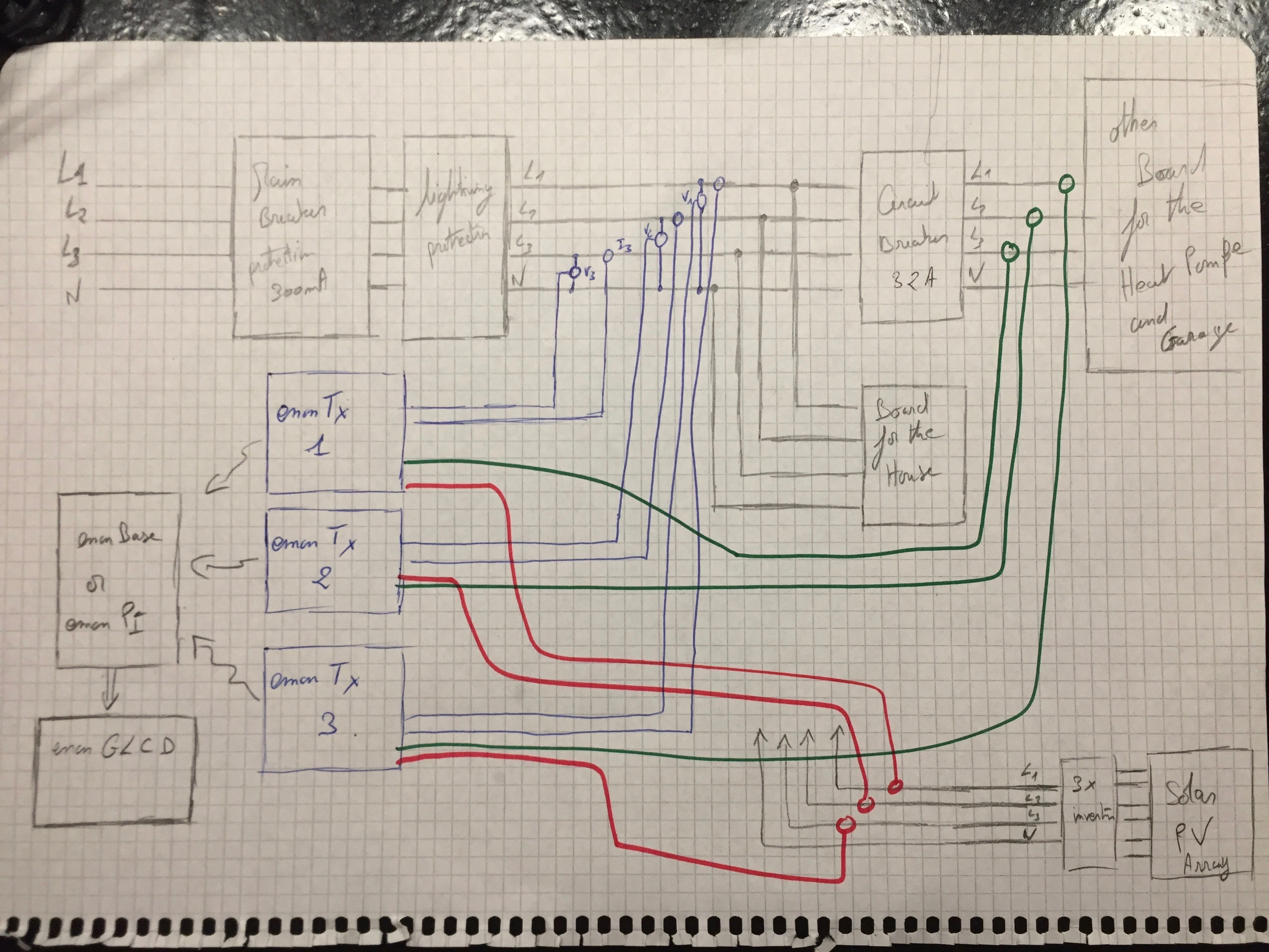
I’ve placed a file with a setup I would like to implement:
To measure the total energy consumption seems to be clear to me with a 3 phases system using 3x emoTx. However as there is other inputs available in the 3 x emoTx, would it be possible to use the other inputs to measure other dedicated energy consumption like:
3 phases going to my garage for mainly heat pump + other stuff
3 phases coming from solar PV array (which I would like to add in the futur).
(see the file link for clearer explanation)
I’m using OpenRemote to monitor all my house (server is on a raspberry 3) and I’m using already emonCms with success to get back on graph temperature, humidity and light. I suppose I don’t need to buy another emonPi or emonBase; just use the one I have, right? (if yes I need to take the 3 emonTX with the wifi module the V3, right ?)
=> If it’s possible, how do I configure the emonTx to send data to my raspberry 3 ? Do I need to reprogram it ?
I would like also to use a emonGLCD but I’m not sure how to configure it. Where could I found some data to install this one ? (I didn’t find for the moment)
Would it be possible to use it with my configuration ?
Last question for the moment. It’s about the current transformer. You have chosen a 100A version; this will be far away from the current I would get for each phases I have. Would it be possible to change it with other one like http://www.lem.com/hq/en/component/option,com_catalog/task,displaymodel/id,U2.00.25.000.0/
If yes, what would be the impact for the emonTx ? (soft modification or also hard?)
Yes.
But I would not connect the three emonTx’s as you have done. I would keep one emonTx For each phase, so that you can measure real power accurately. Therefore:
EmonTx 1 - Voltage from Phase 1, C.T.1 - Main Supply L1, C.T.2 - Garage L1, C.T.3 - PV L1
EmonTx 2 - Voltage from Phase 2, C.T.1 - Main Supply L2, C.T.2 - Garage L2, C.T.3 - PV L2
EmonTx 3 - Voltage from Phase 3, C.T.1 - Main Supply L3, C.T.2 - Garage L3, C.T.3 - PV L3
You can add the ESP8266 to an emonTx, but you will also need a 5 V USB power supply for each emonTx. Then you can send the data directly to your server.
Or you can add an RFM69Pi receiver board to convert your Raspberry Pi into an emonBase, you would then not need the WiFi modules on each emonTx.
The emonGLCD can receive data, but it receives it directly from the emonTx. You can find sketches for the emonGLCD on GitHub. You would need to heavily modify a sketch to receive all three emonTx’s, do any necessary maths, and then you would need to design your display layout. There might not be enough free memory to do all that you want. You might be better to use an old smartphone or tablet that can access emonCMS on your Raspberry Pi.
Yes, you can use that c.t., but you must (a) change the burden resistors in the emonTx, and (b) recalculate the current calibration.
For (a), you need a 62 Ω burden resistor instead of the 22 Ω one fitted (R7 etc, the one with holes for a wire-ended resistor at each end).
For (b) the calibration constant is the current that gives you 1 V across your burden resistor, for you that is 48.41.
Many thanks Rober for your quick feedback.
Few comments:
I’m not sure to get it.
When I read your answer I have the feeling this is what I wanted to do and what I draw in my schematic shown. So I don’t know on my picture where is the mistake if there is one because what you explain is what I wanted to do.
Clear except the 5V USB power needed.
If I add wifi module to emonTx, I need to supply with a 5V USB ? So I will not be able to use the AC/AC power supply and don’t measure properly the voltage of each phases?
If I choose to add the RFM69PI to my raspberry PI, then I don’t need to supply emonTx with 5VUSB right ?(only AC/AC)
Here is the list of product I would like to order:
3 x emonTx V3
(I will buy 2 with Node ID8 and one with Node ID7; I will have to update the NodeID of one)
Node ID : 8 (default)
Enclosure: Fully Assembled
AC Power Adapter: Euro Plug
Yes, when I enlarge your drawing, I see you are right. My apologies.
No, you can have the a.c. adapter to measure voltage and the USB supply for power.
But if you have the RFM69Pi, you do not need a WiFi module attached to your emonTx. The emonTx has a radio transmitter (that is the “Tx” part) for 433 MHz, so it will send the data to the emonBase ( = your Pi + RFM69Pi).
Therefore “If I choose to add the RFM69PI to my raspberry PI, then I don’t need to supply emonTx with 5VUSB right ?(only AC/AC)” you are correct, because the a.c. adapter can supply just enough power for the emonTx without the ESP8266, but it cannot supply enough power for the emonTx with the ESP8266.