Quite probably 
It isn’t something I have gone much into. A work colleague was getting low voltage readings on a home UPS, and the EvoEnergy people tweaked their feed after monitoring. They were worried about motors, i.e. things like fridge compressor motors. .
Thinking about it, I can’t remember seeing a particular change when moving from one adapter to another in the data, but I will go back and do some testing this weekend.
A 5% reduction in voltage will double the life of the bulb, according to Wikipedia.
50 years ago (or thereabouts), the BBC used 6 V, 40 mA lamps for panel indication, fed from a 50 V d.c. supply via a series resistor. The lamp life was said to be infinite, because (a) the filament was under-run and (b) the inrush current was limited by the resistor to little more than the normal running current. (Normally, the peak inrush current on a tungsten filament lamp can be approx 12 – 13 times the normal running current.)
The lighting controller crowd (Lutron, Crestron, Clipsal C-bus etc) reckon they get very very long bulb life. Most program them so that even at “full” they’re only at 90%, and when you turn them on they use the dimmer to ramp them up over a second or two rather than just slam them on, so the room gently comes to life.
I don’t understand what you mean by that, the full calibration instructions are in the ‘Learn’ section.
He’s asking if a Rubber Duck explanation is available…
Tough. If he can’t understand it, he shouldn’t be doing it.
He’s probably not even looked, if the truth be known. I’ve no intention of rewriting all that, nor of producing a video of it.
Hi Bill, pretty much, although I haven’t heard that expression before. It is an excellent phrase, and quite applicable.
Hi Robert, quite possibly. I have a programmer, as part of the kit, but I have never programmed a pi before, so I would need to follow up on that. I certainly didn’t expect you to re-write or produce anything extra. All I was asking is if there happen to already be a more step by step alternative for someone coming relatively new into this area.
As it happens, I have looked at the calibration page a number of times, but shied off, as I haven’t tried to measure mains voltage with my multimeter before, and it isn’t something to rush into. I have a sparky coming into do some work tomorrow, so will ask him to get me a reading, and then I can go to the next step of doing the emonhub.conf changes if needed.
I would also like to say that I have always very much appreciated people’s time and effort that they have provided to answer questions. It has made setting this up so much easier.
To calibrate the emonTx, you don’t touch the Pi. To calibrate the emonPi, you calibrate the “emon” part through the Pi, or you take the emon ‘hat’ off and calibrate it just like the emonTx, except it still needs its power supply - it doesn’t get power from the programmer.
That will be of very limited use - the voltage changes from second to second for me, and varies over a considerable range over the course of a day. Better to ask him to show you how to do it safely, and watch you while you do it the first time.
I was taught half a century ago (and I’m still here), long before all the health and safety laws appeared. I just get on with it, just keep in mind all the time exactly what’s live and what isn’t, and be careful, and don’t let anyone distract you.
If you’re still worried, get one of the plug-in energy monitors. Be sure to check the claimed accuracy before you buy (disregard “typical” - that’s just a sales pitch and means ‘we hope, but don’t guarantee’), and that it can show voltage and current. Whatever you use, your calibration will only be as good as the standard you calibrate against.
Thank Robert,
Good advice.
Jaycar have provided me with the open-circuit voltage of the adapter (post no.9 above), which is 10.4 V
That makes the voltage calibration constant 300.0
(Therefore, @dBC your adapter was out by 1 in 300 - not too shabby.  )
)
Nice. I’ve often wondered if there’s much variation from unit to unit. Did they quote that as a ratio, or was it based on a nominal primary voltage (240V I guess)?
Yes, it’s always based on the nominal input voltage - the number they came up with was 10.4 V. But no tolerance on that was specified. The number I got from your measurement did of course use your measured input and output voltages, and it was wrong - but only by 1 part in 300. I won’t complain about that, and I’m guessing it’s well inside the manufacturing tolerance.
Hi All,
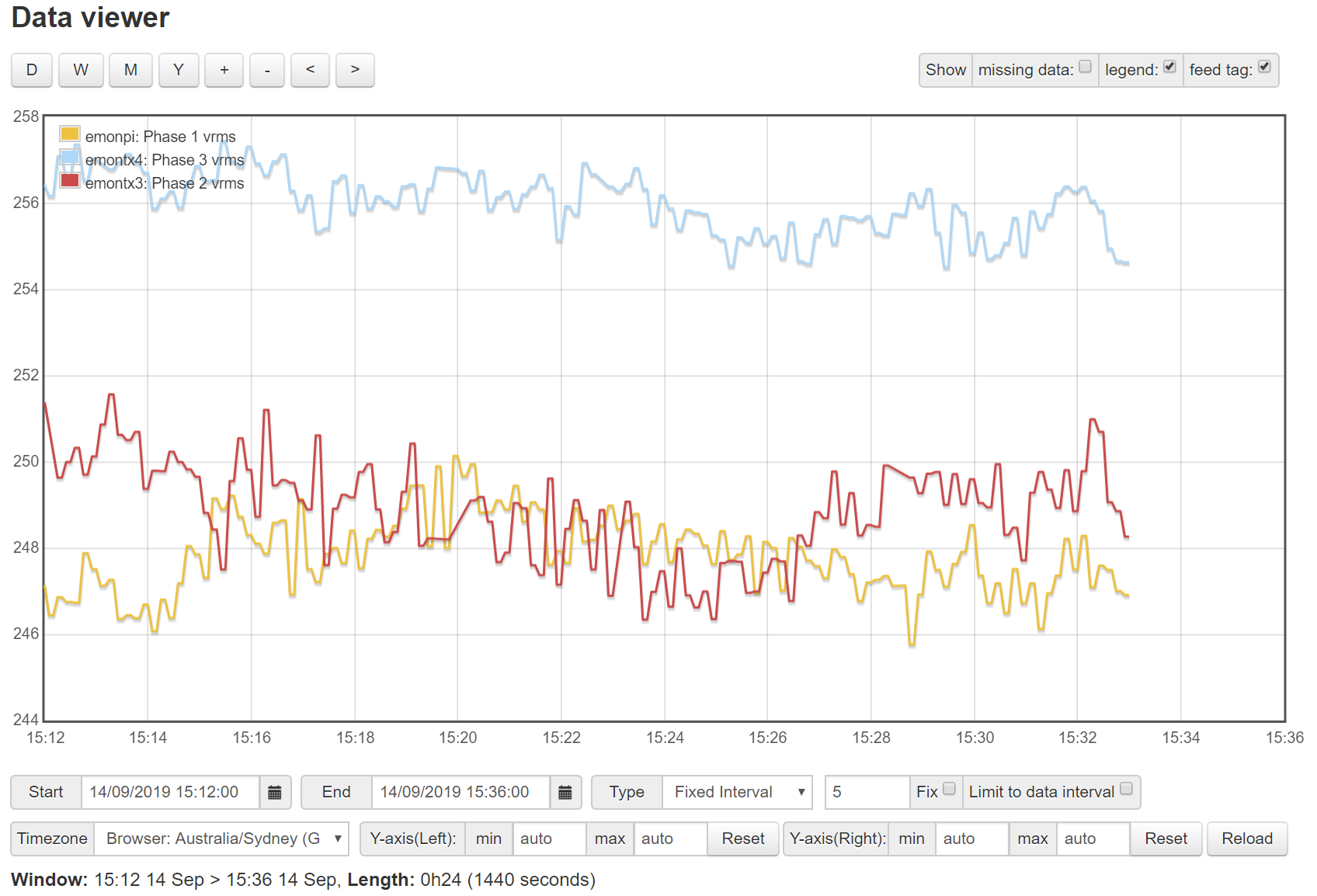
Just getting back to the group with some results. I did some initial comparisons of a multi-meter reading and the reported reading for two of the three phases (those running high). From my initial measurements, one of the OEM UK AC packs is pretty much dead on, and the second is consistently about 1V higher than measured by the multi-meter. I was pretty happy with that.
My local energy supplier (EvoEnergy) are going to be doing a sub tap adjustment, which is scheduled for October 16 2019, so hopefully my voltage will be within the normal limits, and I can have my solar generation not cut out every day.
The data I was able to provide from EmonCMS was very useful, so thanks to everyone involved in the project, plus those that provided me with direct advice.