3 phase solar setup

If it’s not too hard to construct, I’d be interested in a plot of your 3 phase voltages laid on top of each other. I’ve always been a proponent of measuring all 3, although I know in some installations that can be hard to achieve. Any data on just how different they can be is always welcome to help other decide if it’s worth the effort.

I second that. For a long time I’ve been advocating the introduction of a 3-phase unit, with sufficient capabilities to at least monitor two currents on each phase. When such a thing might appear, I don’t know.

Until that does appear, the solutions are as @garnhedryn has done, build your own front end for an Arduino, or live with the assumption that all three phase voltages are equal and use two emonTx’s.

Graph of the three phases.

I have longer logging but disrupted power and mixed up measurements make for slightly messy graphing.

The significant difference between the emonpi and the 2 emonTx’s is probably largely due to the calibration rather than being entirely down to actual difference in line voltage.

Despite the same AC input circuitry and AC adapter, the emonpi and emontx apparently have different Vcal values.

Once upon a time they were both 276.9, possibly each has been independently “fixed” at some point.

This alone could result in around 5% difference regardless of any difference in line voltage or component tolerances etc. I couldn’t say which if any is correct for your setup (in Australia) have you measured any line voltages by any other means to cross ref?

Are they all using identical AC adapters? Are they Aus specific or OEM shop supplied UK ones with an adapter? (I don’t think the shop does Aus AC:AC adapters)

The voltage calibration coefficients for the 3 a.c. adapters from the shop are:

Adapter Type Voltage calibration coefficient for
EmonTx V3, EmonTx Shield V2.5 & emonPi
Ideal Power 77DB-06-09 (UK Plug type) 268.97
Ideal Power 77DE-06-09 (EURO Plug type) 260.0
Ideal Power 77DA-10-09 (US Plug type) 130.0

Note: The values are derived from manufacturer’s data and are subject to normal manufacturing tolerances. The coefficient might be in error by up to ±6% (77DA-10-09 & 77DE-06-09) or ±4% (77DB-06-09) when resistor tolerances are added.

For any other a.c. adapter, the voltage calibration coefficient is the mains voltage that would give 13 V at the low voltage output of the adapter with no load. The latter is important because the adaptor’s output voltage is specified at full load, the no-load voltage can be much higher (it’s 11.6 V rather than 9 V for the 240 V UK one). If the no-load voltage is not specified, then it and the mains voltage must be measured and their ratio used to determine the nominal mains voltage that would give 13 V out.

Under no circumstances must a higher than normal mains voltage be applied to an adapter in order to obtain an output voltage of 13 V.

Correct, but this one has been recommended:
https://www.jaycar.com.au/9v-ac-1-amp-plugpack/p/MP3027
I don’t know the calibration coefficient for it, unfortunately.

Jaycar advise me that the no-load voltage is 10.4 V. That means that the nominal voltage calibration constant is 300.0

That’s the one I used in those early stm32 emonTX shield experiments last year. The one I have (single sample) has a V ratio of pretty much exactly 23. 230V in gives 10V out. I’m not sure how you turn that into a Vcal value, but hopefully you can.

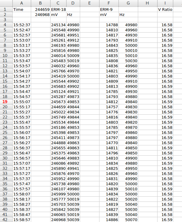
More recently I’ve been doing some dynamic range tests on my energy monitor. It’s designed for direct grid connection with an upper limit of about 270Vrms. I’ve long known it can easily measure all the way down to 90Vrms without changing the dividers, but I was curious just how low that could go. I happened to have one of these at hand so hooked up two monitors sync’d to each other within a few mains cycles, one connected to the mains, the other connected to the output of that transformer. The results were impressive; with 24-bit ADCs you can accurately measure from ~14V up to ~270V with the one set of dividers. But back on this topic, it showed the ratio for that transformer is about 16.58 (again just a single sample).

1 Like

Dead simple: The Vcal value is the mains voltage that gives 1 V at the ADC input. There’s a 13:1 divider inside the emonTx / Shield / Pi, so 13 × 230 ÷ 10 = 299.0

[Edit: Jaycar advise me that the no-load voltage is 10.4 V, so the nominal calibration constant is 300.0 ]

@garnhedryn
That’s the voltage calibration coefficient for the Jaycar adapter - 299.0 300.0

I can’t recommend the M9265A until I’ve checked the input rating of the emonTx power supply - at 14.8 V (with 246 V in), it might be exceeding the rating.

And 246V is relatively low for my 'hood, so you might want to build a bit more of a buffer into that calculation:

The old UK spec was 240 V ± 6% = 225.6 – 254.4 V, so I’d have assumed much the same. It looks as if I wouldn’t have been far wrong. Do you know the nominal centre voltage and the tolerance (and is it the same for the entire continent)?

There’s an Aus/NZ standard centered around 230V for EU harmony, but each state gets to decide when it migrates. Here I found:

The Queensland Government recently confirmed a change in voltage from 240 volts (+/-6%) to 230 volts (+10/-6%) across the state.

That sounds awfully high, that would mean Brian’s corrected voltages would be 257(ish) / 268.97 * 299 = 285.69V for the emonTx’s and 222(ish) / 256.8 * 299 = 258.48V for the emonPi, even the latter is high but 286V sounds way too high, surely?

Is that 10V definitely with no load @dBC ?

It was plugged into the emonTxshield… so pretty close to no load.

I don’t think we’ve confirmed that @garnhedryn is using that VT though. Your analysis makes me think he probably isn’t.

1 Like

Hi Brian

Thanks for that information - should save me a lot of setup time.

Out of curiosity with your voltages, are you using a JayCar 9VAC or the OEM UK one or something else?

Just looking at your graph posted later, the voltages for the EmonPi look pretty much the same as when I first plugged in EmonPi with a JayCar MP3027 9VAC transformer. Compared to voltage measurements from PV Inverter, multimeter and logging from a UPS, the JayCar unit was coming up with about 12% lower voltage reading than ‘real’. Plugging the UK one in gave about 4% lower. Real voltage is typically between 235 and 245 for my connection.

Also of note if anyone else is using the JayCar unit, seems that something is wired differently in that compared to UK unit. When calculating Vrms*I using JayCar unit giving +ve value, changing to the UK version without changing anything else comes up with -ve value (ie I also had to reverse the CT after I plugged the UK unit in to get a correct feed value).

I will post on voltages using the TX’s in my installation when they arrive as some comments later on in this thread note differences in calibrations between Pi & Tx - that may explain large voltage differences between phases.

That’s something that there’s no standard for - even (according to @pb66) amongst supposedly identical UK adapters.

Also, we don’t know the phase error of most adapters, so for best accuracy that needs adjusting too.

Due to space constraints I am using one of the JayCar 9VAC recommended (they are huge) with the emonPI, and two of the OEM UKs (smaller but with an adapter for AU plugs). Looks like I need to go through a calibration. I had a quick look early on, but was more interested at the time in getting the appropriate feed processors correct. Looks like I need to read the calibration doco more closely.

I know the high phases are actually high, as my solar cuts out at 255V and and is supposed to come back on <253V. They are cutting out pretty much daily, hence I have the local energy supplier monitoring my feeds at the moment. I am not sure I will get a copy of the results. (EvoEnergy for any Australian’s here).

I don’t know about the low phase, other than I used to blow a lot of incandescent bulbs when the house was running only on that phase, and that is considered a bit of a warning sign that the voltage is low. I changed to fluro and now LEDs, so don’t have that problem

That sounds like an old wives tale to me. Lamp life for an incandescent lamp is proportional to something like the inverse 4th power of voltage (I forget the actual number) - so reduce the voltage by about 10% and the lamp life goes up significantly. Likewise, removing the inrush current has much the same effect.

Quite probably :slight_smile:
It isn’t something I have gone much into. A work colleague was getting low voltage readings on a home UPS, and the EvoEnergy people tweaked their feed after monitoring. They were worried about motors, i.e. things like fridge compressor motors. .

Thinking about it, I can’t remember seeing a particular change when moving from one adapter to another in the data, but I will go back and do some testing this weekend.

A 5% reduction in voltage will double the life of the bulb, according to Wikipedia.

50 years ago (or thereabouts), the BBC used 6 V, 40 mA lamps for panel indication, fed from a 50 V d.c. supply via a series resistor. The lamp life was said to be infinite, because (a) the filament was under-run and (b) the inrush current was limited by the resistor to little more than the normal running current. (Normally, the peak inrush current on a tungsten filament lamp can be approx 12 – 13 times the normal running current.)

The lighting controller crowd (Lutron, Crestron, Clipsal C-bus etc) reckon they get very very long bulb life. Most program them so that even at “full” they’re only at 90%, and when you turn them on they use the dimmer to ramp them up over a second or two rather than just slam them on, so the room gently comes to life.