3 phase monitoring anomalies

Hello all. I recently setup an EMonPi2 to monitor the power usage at my shop and I’m not certain that I completely understand the data I am seeing nor am I completely certain that I have everything installed correctly. actually I’m pretty certain that I have a couple clamps on backwards.

This question is turning out to be a little longer winded than I had intended, but I want to make sure I give enough context.

We have a 200amp 3 phase 208v service, and I run a couple CNC machines for my business. I am trying to figure out if I have enough capacity to put another machine in the building on the current service, and I am trying to figure out how much each machine costs to run.

I have 3, 200 amp clamps around the main feeds to my panel and individual clamps sized according to the breaker rating on each line of the circuits for my machines.

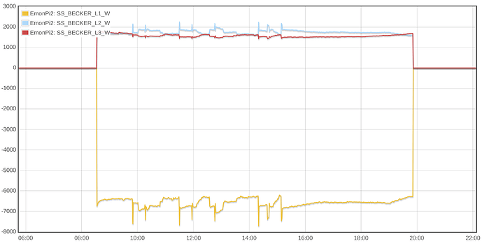
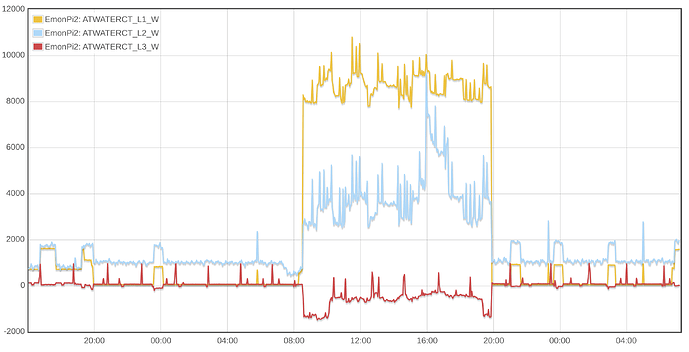
Yesterday I ran a normal day’s production, and got the follow data for the main service power:

I assumed when I initially started getting data that the L2 power was higher than the L1/L3 power due to some unbalanced load in the shop. at the time (20:00 on the graph for example) the only things running in the shop was the lighting, office fridge/computers/etc and main office airconditioner. The AC unit has a 50 amp 3 phase circuit, which I plan on monitoring in the near future. I figured 1kw on a single phase wasn’t too much imbalance.

What I didn’t notice and what becomes even more apparent at 8:00 the next day is that L3 was recording both positive and negative values. At 8:00 the L3 power goes negative, and the power imbalance between L1/L2 becomes about double.

All of this is very confusing to me. I’m not certain why a current clamp can read positive AND negative values, nor am I certain that I can trust so much power imbalance to be accurate.

If I drill into the individual components of my CNC machine(s) I get similar but still confusing information.

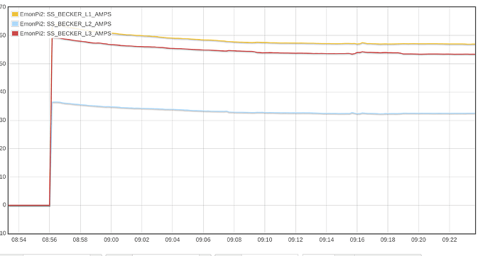
The largest power consumer of the machine is the Vacuum pump. It’s a Becker 17.7HP VLTF pump. The manufacturer says that at 3PH/208V it should need 55amps. I have it on a 100amp breaker, and am monitoring it with 100amp rated clamps.

The L1 clamp in this image is obviously installed backwards (though I believe I oriented them all the same direction when I installed them) and I believe I have the L1/L2/L3 mis-labeled. (I need to double check, but I think I have L1/L3 labels backwards)

What is concerning to me is the magnitude of difference in the power consumption on the phases. Why would I see one phase at 6500W and the other two around 1800w?

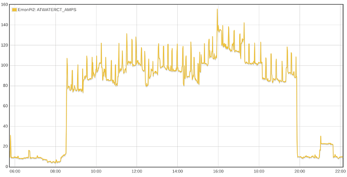
Since I ultimately was interested in if i had enough capacity to add another machine, I added a feed to calculate consumed amps for the whole shop based on the main L1/L2/L3 power inputs

which gives me this graph:

Since some of the underlying amp feed calculations are negative, this graph is a little lower overall than I think it potentially could be. but I’m also not certain that this is the proper way to do the calculation.

I guess ultimately, I have two questions

  1. Are the power measurements that I am seeing accurate and if so are they concerning?

  2. Am I calculating the amp-draw of my equipment/shop properly?
Since I’m new here the forum wouldn’t let me post more than 3 images in my initial topic.

Here are the feed configurations I used to produce the AMP graph at the end of my original post:


These produce the following feeds
ATWATERCT_L1_W
ATWATERCT_L1_AMPS
ATWATERCT_L1_kWh

ATWATERCT_L2_W
ATWATERCT_L2_AMPS
ATWATERCT_L2_kWh

ATWATERCT_L3_W
ATWATERCT_L3_AMPS
ATWATERCT_L3_kWh

ATWATERCT_W
ATWATERCT_kWh
ATWATERCT_kWhd

And as I mentioned, I use a virtual feed to sum all of the L1/L2/L3 AMP feeds together into a TOTAL amps feed for the shop.

Welcome, Clint, to the OEM forum.

You should be able to now, I’ve promoted you.

A current transformer by itself cannot read a negative value, the same as your ammeter on a.c. cannot. But combine it with a knowledge of the voltage and you can then know the direction of Power Flow, and this is what the positive and negative power values indicate.

The first question relating to your measurements: do you have the 3-phase 4-wire version of the emonVS supplying the line-neutral voltages to your emonPi2? You must have this to measure the phases accurately.
The second question (or observation): The emonPi2 and emonVs know nothing about phase rotation. As far as they are concerned, it is 3 single-phase systems until you measure line-line currents - and even then, phase rotation doesn’t come into it. But of course, you must correctly pair up the voltages and currents so that both relate to the same phase. The default pairings are defined here: Firmware — OpenEnergyMonitor 0.0.1 documentation.
Third (hopefully silly) question: You aren’t accidentally measuring the neutral instead of L3, are you?

To check the orientation of the c.t’s, put them all on the same cable. The “correct” one for that phase will measure the true power, the other two will measure half that and negative when they are correctly oriented.

You need to do the maths in the last phase going down the Inputs page of emonCMS, when the other two phases are known for that sample period - else you get 10 seconds old values for L2 & L3 (assuming they go L1 - L2 - L3 down the Inputs page). Other than that, what you have looks OK.

That looks OK to me

Or you could do this in the L3 Inputs page using +Feed for L1 & L2. I don’t know if there are timing considerations with the Virtual Feed - maybe @nchaveiro can enlighten us?
.

Only you can know this for certain - but if most of your heavy machines have 3-phase motors, it doesn’t look right to me. With all machines off and only lights, coffee machine etc working, it may well be a totally different story.

[I’m going to have limited time here for the next couple of days - so I’m not ignoring you if you have any more questions.]

Yes, I have the 3phase 4 wire emonVS - sorry, I should have specified that.

This is one of the suspicions I had in the back of my mind - I am not 100% certain that I have the L1/L2/L3 order correct for all of the circuits - and consequently the voltages could also be out of order for the calculations as well. That would/could explain the vast difference between some of those phases. I am definitely not measuring the neutral line.

Ultimately the L1/L2/L3 nomenclature is just to tell the different lines apart, correct? I know they have a technically correct definition, but What actually matters is that the same line I have plugged into the L1 on the emonVS is the same line that is being monitored with the current clamp on CT1 (same/following for L2/CT2 etc…)

or am I misunderstanding?

I’ll go through the CT clamps and ensure the proper phase and orientation again. This is probably the largest contributor to my problem.

That makes a whole lot of sense. I’ve not looked at the code/implementation, but if it is evaluating inputs as they arrive as opposed to once all inputs are read I can see how that could be problematic for accuracy when having interdependent calculations.

AFAIK virtual feeds, just read/sum the same time-period for all referenced feeds and present that as a facade that looks like a regular feed. They aren’t (again, afaik) usable as targets for the +FEED option on the input processing, so I don’t know that timing would be a problem.

I’m not sure how I could accumulate total AMP draw as part of the input processing. I broke it out into individual L1/L2/L3 feeds because I figured I would need to divide each by their corresponding voltage (V1/V2/V3) to get an accurate amp rate on each line – the sum of which is the total amp usage. the way the input processing works I don’t see how I can do the divisions followed by the additions in the proper order of operations.

Technically, everything in the shop is working - so I guess the reality can’t be that bad. It’s likely measurement error making it look so strange.

My large CNC uses two large 3 phase motors, the vacuum (17hp) on a contactor to start/stop and the other (10hp spindle) on a VFD with programmatic variable control. The motion control of the machine runs on 208v 2 phase (two legs of the 3phases) but doesn’t draw anywhere as much power as the other two.

The other CNC runs on a single 50A 208v 2 phase circuit, using VFDs for it’s vacuum and spindle all running on that circuit. (it’s considerably less powerful :frowning: – hence why I’m looking to see if I can upgrade to a larger machine )

The AC unit for the space also has a 50amp 3 phase circuit, but thats not monitored currently (different issue)

Thank you so much for your help on this. I really do appreciate it.

Not quite - it also defines the phase rotation, i.e. Taking the positive-going zero crossing of L1 as your reference, L2 is expected to do the same ⅓ cycle (5.55 ms) later, and L3 the same ⅓ cycle after that. This is what defines the direction your motor will rotate - as you well know, swap any 2 lines on the motor terminals (so the phase rotation goes L1-L3-L2) and the motor goes the other way. There’s no way to absolutely determine which incoming line is L1. It’s probably the one coming off the terminal labelled L1 on their final transformer, but you don’t need to know. It’s only the order that’s important.

Exactly so. And as I wrote above - if the power is half what you expect and negative, you’ve got the c.t. on the wrong phase for the voltage it’s paired with. (By ‘half’ I mean approximately. It’s exact with p.f. = 1, but only roughly if the p.f. is anything else.)

1 Like

After going through the phases and clamp orders I think I have the majority of my issues solved…

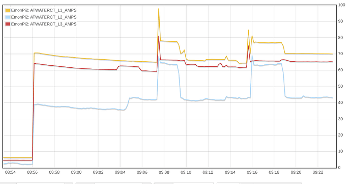
This is the overall building service, showing a couple minutes before we startup and running over about 30 minutes

All of the phases are positive and seem to follow in the right direction. The big question now, is why is my L3 phase 30 amps lower than the other two.

It’s definitely due to my CNC’s vacuum pump:

So I guess I need to figure out why… sigh…

I am still a little fuzzy on how to determine if I have enough capacity to add another machine to my shop. if I have a 200 amp service, does that mean I am capped out at 200amps per phase? (assuming everything is balanced of course)

Thank you so much for helping a newb out. I really appreciate it

:+1:

Hopefully silly questions again: Are the three c.t’s the same rating? and are their calibrations in emonHub (the “scales = …” values) and in the front end via emonCMS all the same? If yes to all, and a clamp ammeter shows the same as the c.t’s, then it’s something only you can sort out ‘hands-on’. If not, is the c.t. dirty on the mating faces of the core, is it closed properly and the cores are not damaged? If all looks good and there’s no other visible reason, you might have a faulty c.t.

I think your practical limit is a lot lower than that (your supply is rated totally differently to ours) but @Bill.Thomson knows more about the US system than I do, so he should be able to advise you.

I’ve got 3 of the 200amp CTs on the building main service and 3 of the 100amp CTs on the equipment circuit. and I did check the CT config:

Loading configuration, list (l) command sent:

firmware = emon_DB_12CT
version = 1.2.0

hardware = emonPi2
voltage = 3phase
vCal = 101.30
iCal1 = 200.00, iLead1 = 3.20
iCal2 = 200.00, iLead2 = 3.20
iCal3 = 200.00, iLead3 = 3.20
iCal4 = 100.00, iLead4 = 3.20
iCal5 = 100.00, iLead5 = 3.20
iCal6 = 100.00, iLead6 = 3.20
iCal7 = 50.00, iLead7 = 3.20
iCal8 = 50.00, iLead8 = 3.20
iCal9 = 50.00, iLead9 = 3.20
iCal10 = 20.00, iLead10 = 3.20
iCal11 = 20.00, iLead11 = 3.20
iCal12 = 20.00, iLead12 = 3.20
pulse = off
RF = off
datalog = 9.80
json = off

I am not clear on the iLeadXX values, but this is how the unit came configured from the openenergymonitor shop.

the scales= values I am also not clear on. the emonhub docs reference a “node 5” setup for the emonpi2 config should be present in the emonhub config, but I don’t see any such configuration in either of my emonpi2 instances:

#######################################################################
#######################      emonhub.conf     #########################
#######################################################################
### emonHub configuration file, for info see documentation:
### https://github.com/openenergymonitor/emonhub/blob/emon-pi/configuration.md
#######################################################################
#######################    emonHub  settings    #######################
#######################################################################

[hub]
    ### loglevel must be one of DEBUG, INFO, WARNING, ERROR, and CRITICAL
    loglevel = DEBUG
    autoconf = 1
### Uncomment this to also send to syslog
# use_syslog = yes
#######################################################################
#######################       Interfacers       #######################
#######################################################################

[interfacers]
    ### This interfacer manages the RFM12Pi/RFM69Pi/emonPi module
    [[EmonPi2]]
        Type = EmonHubOEMInterfacer
        [[[init_settings]]]
            com_port = /dev/ttyAMA0
            com_baud = 115200
        [[[runtimesettings]]]
            pubchannels = ToEmonCMS,
            subchannels = ToRFM12,
    
    [[USB0]]
        Type = EmonHubOEMInterfacer
        [[[init_settings]]]
            com_port = /dev/ttyUSB0
            com_baud = 115200
        [[[runtimesettings]]]
            pubchannels = ToEmonCMS,
            subchannels = ToRFM12,
            nodename = emonTx4
    
    [[SPI]]
        Type = EmonHubRFM69LPLInterfacer
        [[[init_settings]]]
            nodeid = 5
            networkID = 210
            resetPin = 24
            selPin = 16
        [[[runtimesettings]]]
            pubchannels = ToEmonCMS,
    
    
    [[MQTT]]
        Type = EmonHubMqttInterfacer
        [[[init_settings]]]
            mqtt_host = 127.0.0.1
            mqtt_port = 1883
            mqtt_user = emonpi
            mqtt_passwd = emonpimqtt2016
        
        [[[runtimesettings]]]
            pubchannels = ToRFM12,
            subchannels = ToEmonCMS,
            
            # emonhub/rx/10/values format
            # Use with emoncms Nodes module
            node_format_enable = 0
            node_format_basetopic = emonhub/
            
            # emon/emontx/power1 format - use with Emoncms MQTT input
            # http://github.com/emoncms/emoncms/blob/master/docs/RaspberryPi/MQTT.md
            nodevar_format_enable = 1
            nodevar_format_basetopic = emon/
            
            # Single JSON payload published  - use with Emoncms MQTT
            node_JSON_enable = 0
            node_JSON_basetopic = emon/
    
    [[emoncmsorg]]
        Type = EmonHubEmoncmsHTTPInterfacer
        [[[init_settings]]]
        [[[runtimesettings]]]
            pubchannels = ToRFM12,
            subchannels = ToEmonCMS,
            url = https://emoncms.org
            apikey = 98f1c060c90bb2c961e04cb69b2b217f
            senddata = 1    # Enable sending data to Emoncms.org
            sendnames = 1    # Send full input names (compression will be automatically enabled)
            interval = 30    # Bulk send interval to Emoncms.org in seconds
    
    [[DS18B20]]
        Type = EmonHubDS18B20Interfacer
        [[[init_settings]]]
        [[[runtimesettings]]]
            pubchannels = ToEmonCMS,
            read_interval = 10
            nodename = sensors
# ids = 28-000008e2db06, 28-000009770529, 28-0000096a49b4
# names = ambient, cyl_bot, cyl_top

#######################################################################
#######################          Nodes          #######################
#######################################################################

## See config user guide: https://github.com/openenergymonitor/emonhub
## If autoconf is enabled above, node configuration will automatically
## populate based on templates listed in available.conf

[nodes]
    [[23]]
        nodename = emonth2_23
        [[[rx]]]
            names = temperature, external temperature, humidity, battery, pulsecount
            datacodes = h, h, h, h, L
            scales = 0.1, 0.1, 0.1, 0.1, 1.0
            units = C, C, %, V, p
    [[24]]
        nodename = emonth2_24
        [[[rx]]]
            names = temperature, external temperature, humidity, battery, pulsecount
            datacodes = h, h, h, h, L
            scales = 0.1, 0.1, 0.1, 0.1, 1.0
            units = C, C, %, V, p
    [[25]]
        nodename = emonth2_25
        [[[rx]]]
            names = temperature, external temperature, humidity, battery, pulsecount
            datacodes = h, h, h, h, L
            scales = 0.1, 0.1, 0.1, 0.1, 1.0
            units = C, C, %, V, p

I’ve not checked with a clamp meter yet - thats on the list for later today - but since I get the same behavior and relative values on the same lines between the main feed for the building and the equipment circuit, I am prone to believe the clamps are functioning properly, though maybe I am still missing something in the configuration.

If the clamp-meter agrees with the CT Clamps/monitoring I suppose I’ll need to get an electrician out here to help me figure out where the problem could be.

I don’t have an emonPi2, so I can’t check what’s actually happening. But the screenshot and the file infer that the data format now used in the Pi2 doesn’t require a Node Definition. If this is the case, then ignore the bit I wrote about the scales= values.

These correct for the phase error of the two transformers. Every transformer has a phase error - it’s down to how the magnetics work. For a power transformer, it can usually be ignored. But when you are measuring power, any difference in phase error between the voltage transformer (AKA emonVs) and the current transformer leads to the power factor being wrong. If the p.f. is close to unity (as you hope it will be), the error is likely to be not measurable and inconsequential. If the power factor is poor to awful (close to zero), then a small error in the measurement will have a large effect on the value of power factor reported. If that situation arises and you perceive the p.f. to be inaccurate, we can do something about it. (I believe Trystan has assumed the phase error of the emonVs is negligible, so the value is the phase error in degrees of the c.t. only. It does in fact vary according to the magnitude of the current.

Now that you have your system pretty much set up, I strongly suggest you set this to zero. It has caused a lot of trouble for many users because of its propensity to generate spurious inputs.

The term is indeed a source of confusion for many.

Specifically, it means the “weakest link” in your Service Entrance Wire, Meter Base, Meter,
Main Breaker, Load Center (circuit breaker box)
“chain” is rated at 200 Amps,

more info about how to determine your maximum continuously available current here:

The distinction of transformer capacity vs availability makes sense, and adds yet another thing I need to look into for this building. The transformer rating is one thing, but also how much capacity are my neighbors in the building(s) also using.

sizing the CT to the actual usage of the house vs the load center breaker rating also makes sense – the closer the CT is to actual usage, the more accurate it would be able to measure the smaller variances/changes in loads.

I’m really trying to understand how to determine if I need to upgrade the load center/service wiring/etc in this building to support more machines or if the current set up is sufficient as it is. (and now, also wondering if the transformer can even support more - if not, I assume that $$ would be astronomical)

if the main load center is “capped” or “rated” at 200amps, how do I determine how many amps I am using?

I am somewhat fuzzy on the finer details, however from my understanding

In a standard US split-phase (110/220v house service) all of the load for a given circuit is carried somewhat equally between the line and neutral or between the two lines. To measure amp load, you measure one of the lines in the circuit. for a 110v circuit, 10 amps on the one line means the circuit has 10 amps - simple… for the 220v circuit, again, 10 amps on one of the lines means the whole circuit is using 10 amps. so for my hypothetical two circuits I would be using a total of 20 amps (though technically one phase would be more loaded than the other). Hopefully this is all mostly correct. if not, the rest of this is going to sound like a rambling mess.

With 3phase, for single, phase circuits I assume it works the same way - 10 amps is 10 amps. but when you throw all three phases in the mix for my large motors and airconditioner things seem more complicated to me. maybe they really aren’t complicated. I can measure the amp draw on each phase, which for my current measurements shows 50 amps approximately per phase. Would I consider that motor to be drawing 50 amps total, or would I consider that motor to be drawing 150amps total? If the load center is rated for 200amps, does that mean that theoretically I should be able to pull 200amps per-phase or does that mean I’m limited to 200 amps across all phases.

Does this make sense? or am I really over thinking things?

Thanks again for all the help! This has been one of the better forums I’ve participated in.

1 Like

All my experience has been in the UK. I would always say or understand “motor is drawing 50 amps” to mean total if it was a single-phase machine, and per phase if it was a 3-phase machine, maybe adding “per phase” if I thought there might be some confusion. I’d never say “150 A” without qualifying it with “across 3 phases”. Really, that’s 50 A in the wire, however many there are.

This doesn’t apply to powers of motors or VA ratings of transformers - this always means the total across all phases - and there’s an inherent assumption that the balance between phases is reasonable. On that basis, your 200 A load centre can deliver a bit over 120 kVA, and if the transformer supplies just your facility, its rating would be around that, quite possibly a little less because you wouldn’t draw that continuously.

I think you should ask your electricity provider. They’re the only people who are in a position to know. You might be able to make some intelligent guesses if you know what your neighbours’ demands are, and what the label on the transformer says.

One way to hold cost down would be to add another 200 Amp service instead of
upgrading your preset service to say, 400 Amps. A 400 Amp 3-phase load center
costs quite a bit more than a 200 Amp one. You’d have to run new wire from the weatherhead to the meter base and possibly new wire for your “new” machine
if the existing wire to the present machine isn’t large enough to handle the load
the new machine will draw. You’d also need a meter base that will handle the entire
load. Whether or not all of that would be less costly than upgrading to a 400 Amp load
center, I can’t say.

As Robert suggested, your energy provider would be the place to start asking questions
about any upgrade(s) you have in mind.

A quick glance at one of the big box store’s website shows 400 Amp load centers
going for 1000 to 1500 bucks.

As to what you’d be charged for a new transformer bank, that’s one for your provider.