Do I still need the 3-phase firmware?
Namely I get on each of the 3 CT values
Welcome to the forum, Karl.
I don’t know…
But as your country is Austria, then I suspect you do. The present 3-phase sketch is continuous monitoring.
The sketch that is the subject of this thread is single phase only. You can certainly use it on a three-phase system, but you will need one emonTx for each phase.
Thanks for the answer. I have not yet flashed 3-phase firmware but get the original firmare on all 3 phases of data.
Because of the different timing of the three phases, only the phase with the a.c. adapter is reading the correct power. The other two phases will read - for a pure resistance load only - the correct power × -0.5. (i.e. ½ the correct power and negative). For any other type of load, I cannot easily predict what it will read.
so have now flashed the 3 phasig firmware, but now have no input keys in emonsesp. do I have to change in the firmware paramter? or just as I did it just flashing?
Because this does not appear to be related to the new (single phase) continuous monitoring software, I have created a new topic.
I think you need to tell me exactly what you have. All I know is you have an emonTx V3. In the normal setup, it sends the data by radio to an emonTx, and that should work. If you have anything different, you must configure your sketch according to the documentation that was in the zip file that you downloaded.
601/5000
Thank you for your support. I have an emontx 3 with ESP module, I have 3 CT. Since I live in Austria I have a 3-phase power supply. with the original firmware I have on all 3 inputs of my opinion my power consumption. in forum I have something of the 3 phase software read and this synonymous flashed so without changing the original file 1.6 and thus have only 2 ct with data, but in the esp module is not displayed only with the query of the ip address with slash input. So I need the 3 phase software? and what should I change in the original file 1.6.
Yes, you have a 3-phase supply so you must use the 3-phase software in the emonTx V3.
(Without it, the emonTx will not read the correct powers for phases 2 & 3.)
I suggest you begin by setting up and calibrating the emonTx without the ESP8266, and use your programmer and computer to see the results.
When you have it working, connect the ESP8266. To tell it to send the data to the ESP8266, you must configure the 3-phase sketch:
comment this out - otherwise it will send bad data to emonCMS
line 71: // #define SERIALPRINT
line 81: #define EMONESP
The baud rate in the sketch is set to 9600. You must not set it greater than this, and you must change the baud rate in the ESP8266 to 9600. I do not know how to do this, @Simsala can help (in German if necessary  ) He has many emonTx + ESP8266 system working in Germany.
after flash no more data ??. Although I can flash tasmota but I’ll need a course, if I had known that it would be so complicated with the 3phasen software I would have let it off.
All I can say is @Simsala has many systems just like yours working successfully. Hopefully, he will be able to help you.
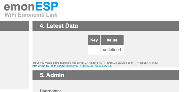
Hi @Terra2000 I’m sorry you’re having trouble. If you have seen this thread, it might be helpful. Basically only one line needs to be changed: Latest data showing blanks/blocks - #10 by matti
If the emontx 3phase firmware is running at higher baud rates, there may be some corruption in the data output. @Robert.Wall: I am not sure how often this happened, but I suspect that it would be a valid compromise to use the firmware with higher baud rates? Otherwise, it would make sense to be able to set the baud rate via the web interface to reduce user frustration.
The problem with higher baud rates than 9600 is that the Atmel '328P processor is so busy handling the sampling and processing the measurements, that the transmitted data is corrupted if you attempt to run any faster.
This was clearly visible even with the Arduino IDE when I was developing and testing the sketch, without the ESP8266. Indeed, I do not even have an ESP8266. I don’t think a compromise is possible, because (IIRC) the transmission fails fairly consistently.
Assuming that @Terra2000 has made the change to his ESP8266 correctly, and that he has configured the sketch correctly, do you have any idea why he is not getting the data?
What exactly did you change in the emonESP firmware? Which program do you use for modifying and flashing? What exactly did you change in the 3phase firmware?
Can you please share the serial output of the emontx?
OpenEnergyMonitor.org
emonTx V3.4 CT1234 Voltage 3 Phase PLL example - Firmware version 1.40
Using RFM69CW Radio
No EEPROM config
Calibration:
vCal = 268.97
i1Cal = 90.91
i1Lead = 2.00
i2Cal = 90.91
i2Lead = 2.00
i3Cal = 90.91
i3Lead = 2.00
i4Cal = 16.67
i4Lead = 0.20
Network: 210
Node: 11 Freq: 433MHz
POST.....wait 10s
'+++' then [Enter] for config mode
0.00 0.000 0.000 0.000 0.000 0.00 0.00 0.00 0.00 0.000 0.0000 0.0000 0.0000 0.0000 300.00 Pulses=1  PLL is unlocked
0.59 0.000 0.000 0.000 0.000 0.00 -0.88 -1.75 0.00 49.942 0.0000 0.0000 0.0000 0.0000 300.00 Pulses=1  PLL is unlocked
0.13 0.000 0.000 0.000 0.000 0.00 -0.00 0.03 0.00 49.893 0.0000 0.0000 0.0000 0.0000 300.00 Pulses=1  PLL is unlocked
0.30 0.000 0.000 0.000 0.000 0.00 0.04 0.03 0.00 49.857 0.0000 0.0000 0.0000 0.0000 300.00 Pulses=1  PLL is unlocked
There was an error in V1.4 that inserted a space character in the output where there should not have been. The present version is 1.6. You must download and use V1.6.
But this in the output
shows me that you have NOT configured the sketch to send the serial output in ESP8266 format. I told you to do this in Post nr. 8. If you do not do things as I instruct, you cannot expect it to work, and you should not complain when it does not. Please read page 3 of the documentation.
RFM69CW
   Defines the mode of transmitting the output data. Permissible settings are:
      RFM69CW   Hope RFM69CW radio module
      SERIALOUT Wired serial connection via the FTDI port (suitable for direct
                            connection to the emonBase or emonPi
          (see https://github.com/openenergymonitor/emonTxFirmware/
           blob/master/emonTxV3/noRF/emonTxV3_DirectSerial/
           emonTxV3_DirectSerial.ino )
      EMONESP    ESP8266 WiFi module
          (see https://github.com/openenergymonitor/EmonESP)
When you get that setting correct, the output should print
Using ESP8266 serial output
instead, and the output will be in the correct format for the ESP8266 to use.
i use 1.6 in the emonTx_3Phase_PLL.ino ( const int version = 14; // The firmware version 1.4)
Yes, sorry, that number did not get changed in version 1.6
But you must still set the output format suitable for the ESP8266. That part has not changed.
// #define DEBUGGING // enable this line to include debugging print statements
// This is turned off when SERIALOUT or EMONESP (see below) is defined.
// #define SERIALPRINT // include ‘human-friendly’ print statement for commissioning - comment this line to exclude.
// Pulse counting settings
#define USEPULSECOUNT // include the ability to count pulses. Comment this line if pulse counting is not required.
#define PULSEINT 1 // Interrupt no. for pulse counting: EmonTx V2 = 0, EmonTx V3 = 1, EmonTx Shield - see Wiki
#define PULSEPIN 3 // Interrupt input pin: EmonTx V2 = 2, EmonTx V3 = 3, EmonTx Shield - see Wiki
#define PULSEMINPERIOD 110 // minimum period between pulses (ms) - default pulse output meters = 100ms
// Set to 0 for electronic sensor with solid-state output.
// RFM settings // THIS SKETCH WILL NOT WORK WITH THE RFM12B radio.
#define EMONESP // The type of Radio Module, or none.
// Can be RFM69CW
// or SERIALOUT if a wired serial connection is used
// or EMONESP if an ESP WiFi module is used
// (see http://openenergymonitor.org/emonnode/3872)