Guys …
Many thx for all yr ideas and suggestions.
Safety is a concern so I do not want to remove covers and probe 400+ volts.
The ground mount PV array (114 panels) & inverter is 100 metres from the house. Between the array and the house is an outdoor heated swimming pool with an ASHP in situ but not yet plumbed or wired. Extension leads are not really feasible.
There will be 3 x emonTx’s - at the inverter, in the pool plant room and at the grid supply meter (house). The site has wifi coverage.
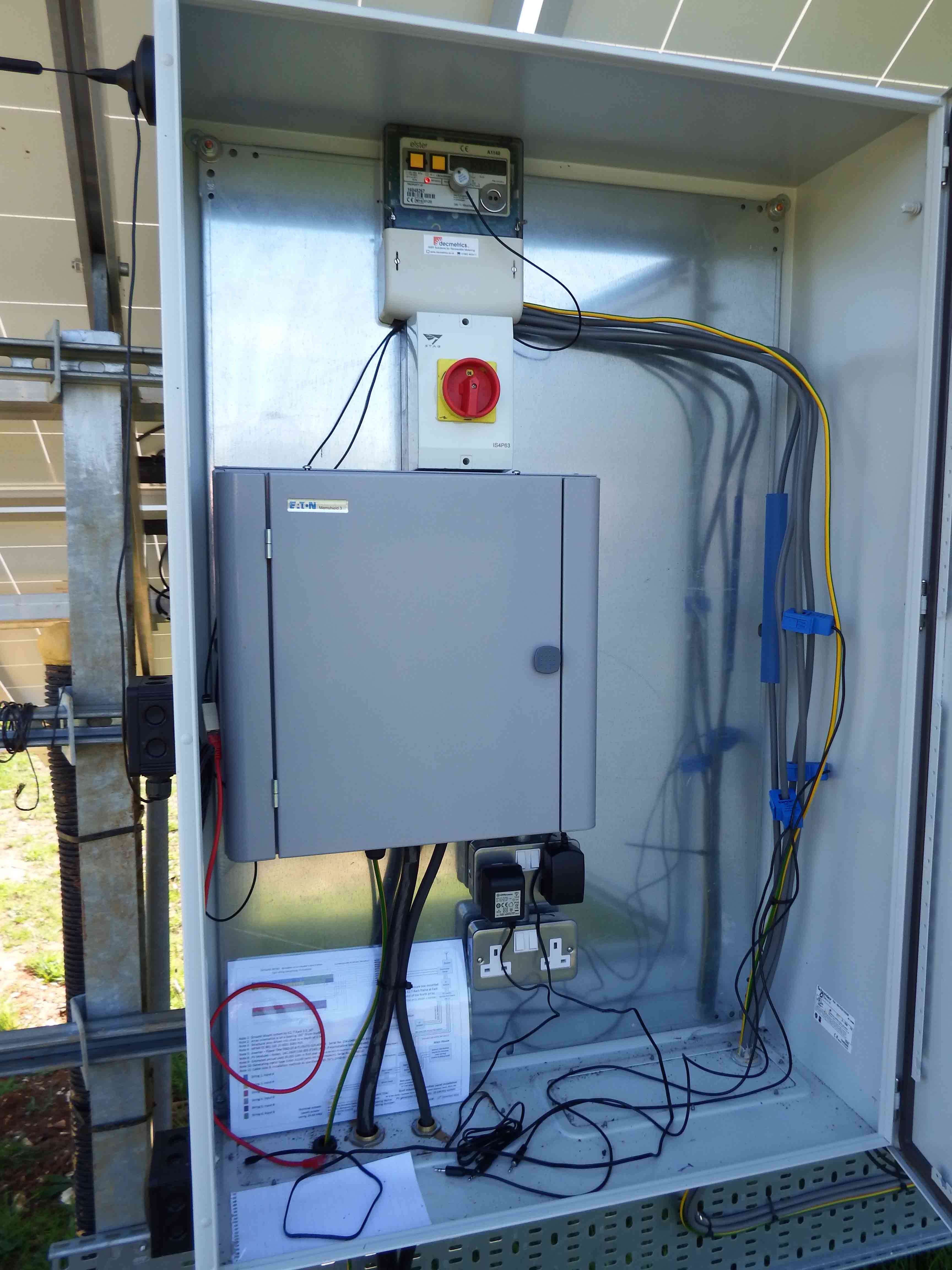
When I open the cabinet at the ground mount PV array, I’m faced with 3 unidentified cables from the inverter to the smartgen meter.
Here will be an emonTx (with 3 phase firmware) serially connected to an RPi running emoncms plus 3 CT’s and a pulse counter on the smartgen meter.
There is also a 13 amp socket outlet (for the ac/ac adapter) connected to one phase but I know not which. See picture …
From an earlier forum exchange with Robert, I understand that at the inverter/smartgen meter, the PF will be close to 1.
Also I assume the power on each phase will be close to equal when generating – correct?
The inverter itself has an LCD panel showing what is currently being generated in total.
Once up & running, I envision applying a simple correction factor (based on smartgen meter pulses) to the phase powers as shown by the emonTx.
So my trial & error questions – if I clip all 3 CT’s to one live cable – what emonTx powers will be indicated if the selected live is not nominal phase 1 (ac/ac adapter phase)?
What will I see if by chance the selected live is nominal phase 1? Is this a way of identifying nominal phase 1?
If so I’d then be left with 2 x unidentified phase live cables and 2 x CT’s. I could try hooking both CT’s to each of these phase lives in turn – what powers would I see? If one were negative would this be the final clue?
To complicate matters, the installation is at my son’s place an hour’s drive away and I’m spending days trying to set up emon gear in my single phase home with no PV where I’ve made an experiment with an emonTx running 3 phase firmware.
I clipped 2 CT’s to my one live phase (making sure they were in same direction orientation). One CT was in CT1 input and the other in CT2. The house consumption was 500 watts approx but varying as indicated by CT1 PowerL1. Then I boiled a kettle …
CT1 PowerL1 3465 watts
CT2 PowerL2 minus 1880 watts (at the same sampling instant)
I switched the second CT into CT3 input, rebooted the emonTx and boiled another kettle …
CT1 PowerL1 3678 watts
CT3 PowerL3 1606 watts (at the same sampling instant)
Is this data in any way helpful or relevant?