I have a generator for a wind turbine with a 3-phase output in a delta configuration, so it doesn’t have a neutral. How do I measure the phase voltage with ZMPT101B ?
Do you really mean “How do I measure the phase to neutral voltage?” All you can do is measure the line-line voltages - I have no concept of a neutral in a 3-phase 3 wire system, which is what you have - unless there’s something (the load it is feeding?) you haven’t told us about.
You can connect three ZMPT101B transformers together with their multiplier resistors in star to measure what the line-neutral voltages would be, but unless the generator’s load is accurately balanced, those won’t be the voltages the load sees.
N.B. You can’t use an emonVs like that, because the power supply is single phase and so it must have a neutral, but you can use emonLibDB and an emonTx4 if you make your own emonVs look-alike with the primary sides of the ZMPT101B connected line-line in delta.
Whatever you do, DO NOT use the ZMPT101B module incorporating an op.amp - on the only circuit diagram of it I’ve found, it exhibits a massive phase shift that makes a mockery of power measurements.
Yes, what I meant is measuring the phase-to-phase voltage at the output of the generator. I have ZMPT101B transformers, how do I make my own circuit to measure the phase-to-phase voltage ?
I will only measure a voltage of 12 VAC, so what should I change ?
I have looked at the diagram, but I am still confused because not all of those components are available in my country. Are there simpler options for the circuit ?
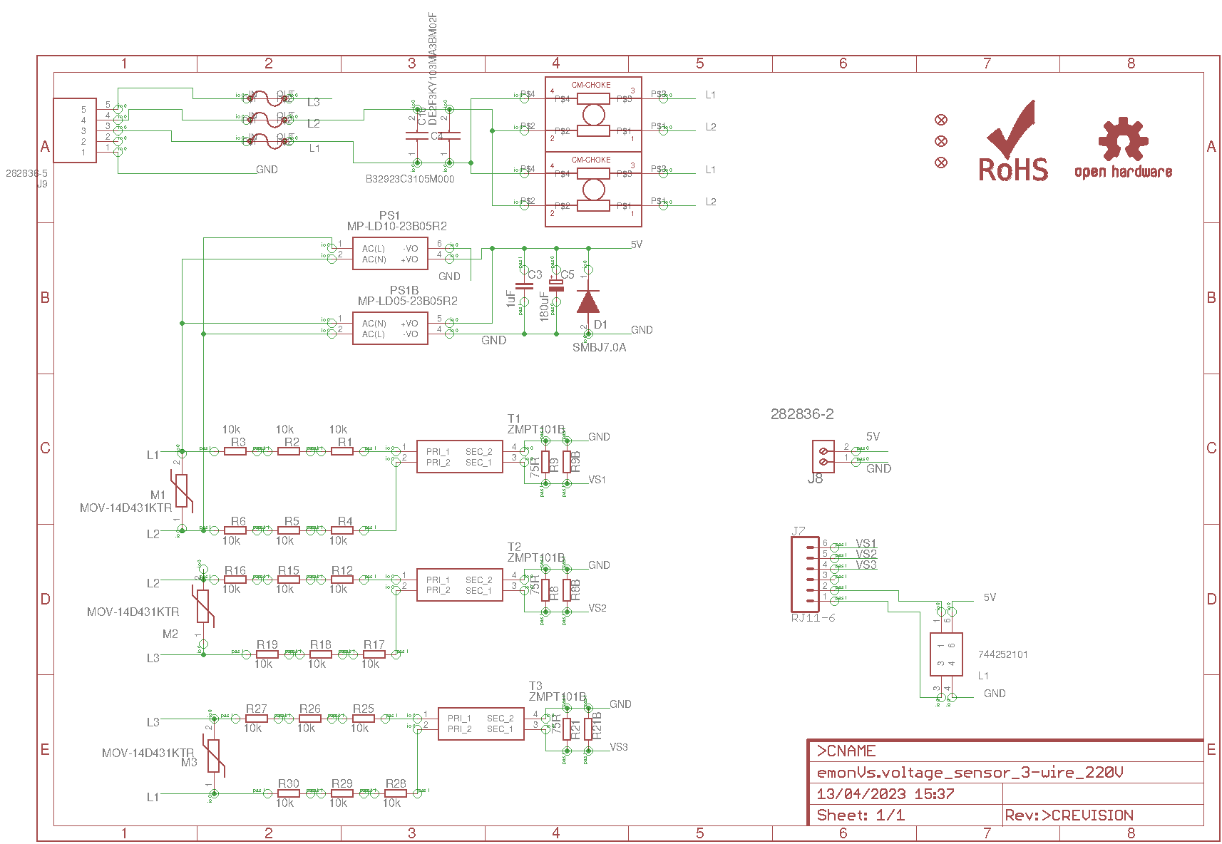
All the parts above the ZMPT101B for Phase 1 (T1, R1,R2,R3 etc) are for the power supply for and emonTx or a Raspberry Pi, so the only parts you need will be the ones around the 3 ZMPTs. Also R9B (etc) is a place-holder for a second parallel resistor in case R9 needs to be changed. There is no resistor fitted for R9B.
For 12 V rms, you do not need 6 resistors R1 - R6, just one single resistor will be safe at 12 V, its value should be 3.3 kΩ to give you about 3.535 mA in the c.t. at 12 V, therefore with the 75 Ω burden shown, you will have 0.333 V out at 15 V line-line from your generator. (0.333 V is good for a 1.024 V ADC input.) You might want to use a pair of 18 V or 22 V zener diodes in place of the MOV to protect the input in case the generator output rises too high - these will clip at 13 V or 16 V rms.
So all you need (3 times) is R1, T1, R9 and optionally two zener diodes to replace M1.
Do you have any other schematic that is simpler, because I still don’t understand the system of the emontx above
Sorry, no.
What is it you don’t understand? Is it because all the connections are labelled but not joined up? For example, all labelled “L2” are really all the same thing. This is a “feature” of Eagle CAD and the way it is used here. I learned to draw electrical diagrams on paper, not a computer, and I don’t like the way the schematic is drawn. Unfortunately, I do not have the time to redraw the schematic for you.
Or, should I be asking: What do you require whatever it is you are designing or working on to do?
Yeah, I’ll try to read from the diagram above, because I’ve just gathered the required components and there are very few references related to the 3-phase delta circuit.
As far as measuring the voltages is concerned, after you’ve connected the primary windings (each with its resistor) in delta, there is really no difference between that and three single-phase emonTx’s. You wire one end of each secondary winding and its burden to 0V, the other end to an ADC input via a coupling capacitor and bias network. See the section “Configuration used in the emonTx V2 and the emonPi” here: Measuring AC Voltage with an AC to AC power adapter — OpenEnergyMonitor 0.0.1 documentation and especially the paragraph near the end starting “For the emonTx4, the a.c. adapter is replaced by a small current transformer …” which is exactly what you have. The ADC outputs will give the L1-L2 voltage on the first, the L2-L3 voltage on the second, and the L3-L1 voltage on the third.
Then to convert the phase voltage, do I just plug it into the delta circuit theory formula?
What do you mean? From your ADC, you will get three numbers representing the three line-line voltages. Those are the voltages which, when you measure the current in a load that’s connected between the same two lines, will give you the power being drawn by the load.
To read the current, can we use the SCT 013 sensor?
What is the value of the current, approximately? There are many different current ratings in the SCT-013 range, from 5 A to 100 A with a 1 V output, and the 100 A SCT-013-000 with a 50 mA current output. The voltage output options do NOT require a burden resistor, the current output version does.
The components I suggested for the voltage give you an output of 0.333 V rms going to the ADC. If you are designing a device to read both current and voltage, I would recommend instead you look at the very wide range of 0.333 V output current transformers that are widely available. You can then use exactly the same ADC input and basic settings for both types of input, making your design much simpler.
Thank you for the advice. I’m sorry for replying because for the past few months I have been trying to make a circuit to read the 3 phase voltage. I have tested each sensor and it is quite good at reading voltage using emonlib for Arduino. but a problem arose when I wanted to read 3 voltages simultaneously. Is there a special library for 3 phases or is the microcontroller I use not powerful enough to process the library? I use Arduino Uno with Atmega328
I think you will not succeed in measuring the voltages “simultaneously” using emonLib. The best you can do is measure the voltage and current for each phase in succession, meaning you will measure 1 phase for about 200 ms, then the next for the same time, then the third.
If you want to truly measure everything simultaneously, then you need to start with emonLibCM, but this is written for one voltage and 5 currents (even though we only use 4), however you can relatively easily change it to read 3 voltages and 3 currents.
Thank you for the advice. I’ll try to tinker with the library first
EmonLibCM_SetADC_IChannel(3, 90.91, 4.2); // 90.91 for 100 A : 50 mA c.t. with 22R burden - v.t. leads c.t by ~4.2 degrees
EmonLibCM_SetADC_IChannel(4, 16.67, 1.0); // 16.67 for 100 A : 50 mA c.t. with 120R burden - v.t. leads c.t by ~1 degree
How do I use the command above if I use SCT013 version 10A/1V
Take a look at the documentation.
Under
void EmonLibCM_SetADC_VChannel(byte ADC_Input, double _amplitudeCal)
void EmonLibCM_SetADC_IChannel(byte ADC_Input, double _amplitudeCal,
double _phaseCal)
a little way down, you will read:
Current amplitude calibration constant: This is the ratio of mains current to the alternating component of the voltage at the ADC input. Default: 90.9 for all channels except logical channel 3: 16.6 and provided that the default channel sequence is unaltered. The unit is the Siemens (1 / Ω).