3-phase board 3 voltages and the BluePill

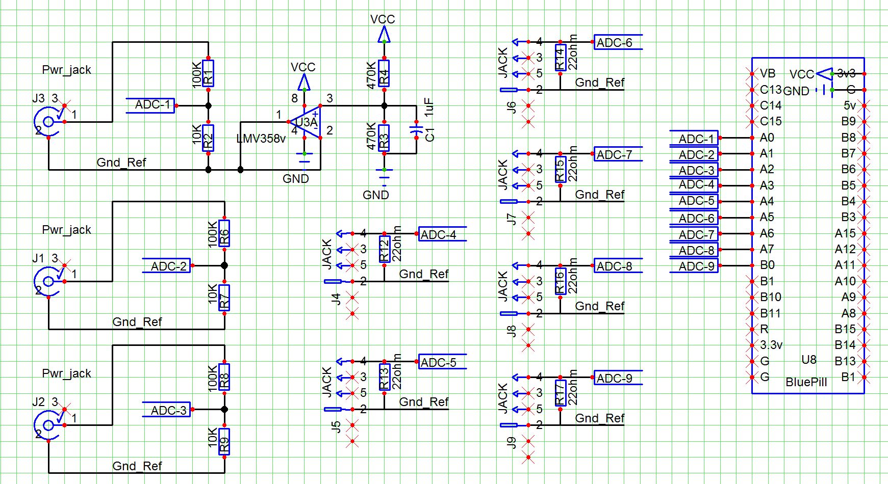
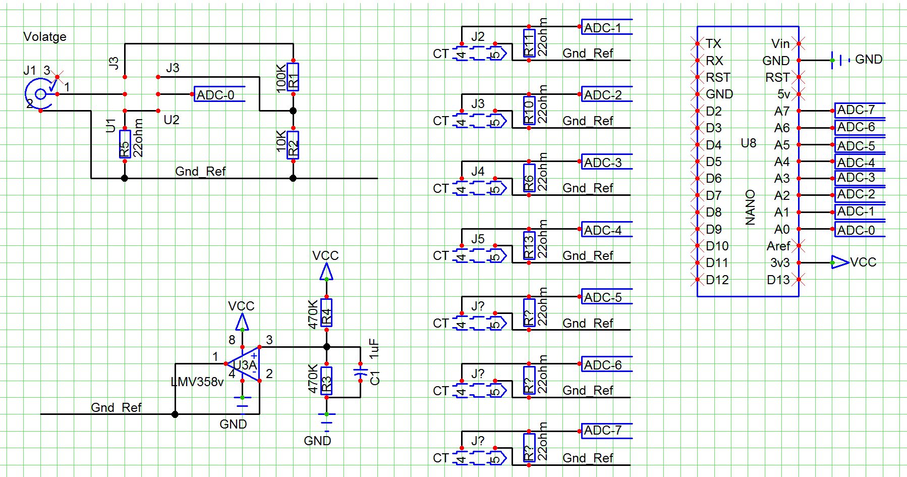
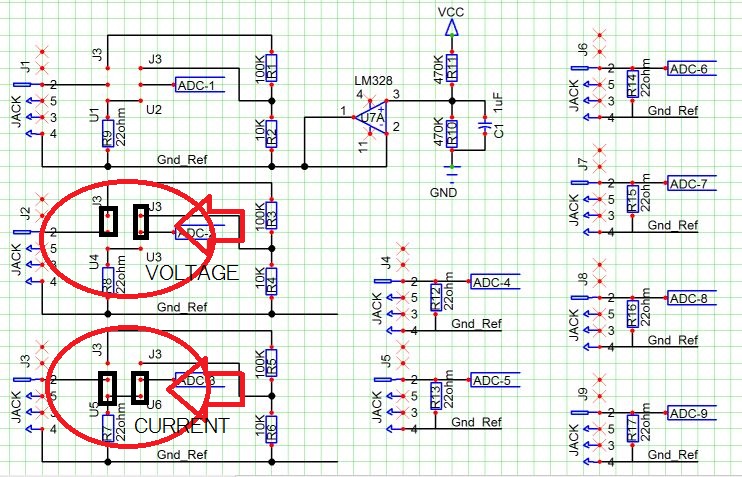
Schematic is my full compliment of 9 ADC inputs, 3 are either/or voltage/current
the other 6 are current only, all share one OP-AMP for reference

My application is for a 3-phase panel
Measure all 3 mains voltages and the 3 mains current
In addition, measure one 3 phase motor.

I am thinking, 9 inputs, 6 with CT’s and 3 for voltage

Using the simple Current sensing is easy, just get the correct range CT’s

Voltage and 3-phase add the twist.

Since detecting a loss of a leg of power is part of my design goals, I want to measure all 3 voltages.
The mains voltage in this particular instance is 480 3-phase. (I’m in the US) It appears that it would be best to measure line voltage (phase to neutral), not phase to phase voltage.

When I have boards made, I get 10 at a time from the board house.

I am thinking that with a few extra pads and some jumpers, I can make a 9 channel all current sensing board. See the first 3 channels.

The plan is to use a BluePill STM-32 based board on the board.
Also, if I have 10 boards, I can see that I will want to populate a second board with all current sensors and it’s own BluePill

One question is how best to have all of these talk to each other. Probably use one ESP8266 as the one that ties them all together and offers the WiFi out.

I will be using the Arduino IDE for these boards.

One of the questions that keeps nagging in my head is to have a separate voltage only board and use the ZMPT101B transformers so as to have one board with the high voltages be separate from the current sensing board.

ZMPT101B

I’d agree with that. If you have a balanced resistive load, the line current is in phase with the L-N voltage, so there’s no need for a 60° phase shift in the software.

I would certainly go down that route. It makes testing on live circuits so much safer. And I’d steer well clear of the modules that have a built-in multiplier resistor - it’s much preferred to use two equal resistors in series, then if one fails to a short, or flashes over, you stand a chance with the remaining one.

And cut a slot in the board underneath the transformer to give you a decent creepage distance between the high and low voltage sides.

Having a double duty input seems to cause me some anguish. what if a CT and a V were both plugged in ?
putting a 3.5mm plug on the voltage or using a gender changer was also not appetizing.

my thoughts are to make 3 voltage inputs.

Can I alter the thread with a question about connecting multiple boards ?

using the Arduino IDE and the Blue Pill, and having one BluePill per board, I would want to have a couple other boards.

the BluePill certainly is fast enough to measure then communicate to the other boards. I would stack them so a simple cable or even a riser jack like the Arduino UNO has would allow them to plug into each other.
share power and signals.

the top of the stack would be an ESP8266 and an LCD.
any suggestions of best way to get these to talk to each other ?

If you’re going to multiple boards, then my suggestion would be three single-phase boards.

If you stay with a “voltage” board and one or more “current” boards, then to be able to measure real power, you must synchronise each sample across 3 inputs (V + 2×I) and share it’s value with whichever board is calculating the average power. Clearly, rms voltage and current don’t suffer that problem and those calculations can be done by whichever processor does the measurement.

But by having one phase per board, all the information for one phase remains inside the one processor, only the result every sampling period (be that every half-second or half-hour) needs to be communicated. Serial, polled by the ‘master’ board, would seem to be an obvious choice for communicating the result - using whichever protocol suits your needs / experience.

If you use the “discrete samples” type of sketch, then MartinR did pretty much what you’re proposing many years back with three emonTx V2s (Full-fat 3-phase monitor | Archived Forum), the master commanding each to start sampling, then receiving the data in turn. But I’d expect with the processing power you have, you’d want to continuously monitor. The new CM library reports the data based on counting mains cycles, so three boards running a variant of that should remain in sync indefinitely.

To review : a 3 board arrangement, with an STM32 ( or Nano?) with one channel input for voltage per board. The remainder of the available ADC pins for current.

  • each board will have one voltage so when used in a 3-phase application, one board would use one phase as the voltage reference and the current inputs would be referenced to that voltage.
    QUESTION : using an op-amp to create the reference voltage for all the currents sensors. Is there a practical limit to the number of current sensors ? I see the use of no more than 20, but since one board would have 10 ADC inputs (STM32) it would not be difficult to put on op-amp on each board.
    I am currently working with an Arduino NANO as I have one, the STM32 is somewhere in the Pacific Ocean on a pleasant ocean cruse.

Not really. The op.amp. is there to provide a low impedance voltage source for the mid-point. The current it needs to provide is the charging current for the sample & hold capacitor in the ADC - ideally it doesn’t move by more than ½LSB as the multiplexer switches.

That is good news.

using one voltage input with the layout that would the standard wall-wart transformer seems the best way create that bit.

The voltage input would need to be made so that whatever the source, it matches that of the basic wall wart transformer.

I am still not set on how to get 480 VAC in the US, connected in the circuit panel and brought out in a low AC voltage for the voltage sensing.

Hi Dave,

277 VAC to 24 VAC HVAC Control Transformers are readily available at reasonable cost. e.g.

or

Do you want 480 V, or 277 V? If you’re interested in the overall power, it doesn’t matter whether you use L-L voltage or L-N voltage. But if you’re treating each leg as a single-phase system, then you want the L-N voltage of 277 V, otherwise, you’ve got a nasty phase shift between current and voltage to make life difficult.

One small point to think about when laying that out on a p.c.b: Make it easy to substitute a different value of burden. The range of c.t’s available means that a range of burden values is also needed.
Much the same goes for R1 in the voltage sensing circuit - then you can easily accommodate any (sensible) voltage input.

And I suggest changing “Gnd Ref” to “Bias Ref” to avoid confusion. Yes, it is an a.c. ground, but not a d.c. one.

I am not sure of the best route, any help is very welcome.

line voltage (line to neutral) would be 277VAC
phase to phase voltage on a 3-phase system would need to be 480

since one board would reference on voltage and ( I assume ) would act as if it were measuring a single phase, then the 277VAC transformer is perfect.

when running a 3-phase motor, each coil of the motor would represent one leg, and (I assume) could be measured independently, then summed for total motor current.

the need to measure each voltage is to determine if there is a voltage problem that might cause the motor to run with only 2 phases.

==============

I could install a new box to house the 3 transformers and then have the output sent to the enclosure with the data monitoring.

I do like the idea of separate enclosures. or, possibly putting the transformers on the case of the load center (breaker panel) and keeping all the higher voltages separate from the lower voltages.

Probably not. Internally, the motor windings are most likely connected in delta.

Yes, but more to the point, it gives you a more direct relationship to what might be going on inside the motor.

Erm… no. When you lose a phase, the motor is running on one phase, believe it or not.

Where you put the transformers is really a matter of convenience. As long as the low voltage side is fused appropriately to protect the transformers against cable damage, the current draw is negligible so the wires can be long and thin with no ill effect. But beware of interference and pick-up, so you might want conduit or screened cable if it’s a long run and/or there are interfering sources close by.

BURDEN RESISTOR : seems there are a couple of choices. the SCT-013 has a circuit board inside of the housing. one option seems to fix the burden at that point. then the CT is scaled and cannot be changed.

The other seems to be to put on a pair of burden resistors on the PCB and use a 3-pin jumper. that would offer 3 choices. this way the range can be changed.

I envision that a 200 amp might be needed and I know some 20 amp CT’s will be needed.

The details about the current transducer show the possible use of an op-amp to alter the range. this is also a viable option.

for phase-1 the best thing would be to use a tandem resistor layout with jumpers. creates a lot of options.

Thanks for bringing that up.

Even simpler than jumpers, and probably safer: mount the burden resistor on posts like this - then you can change it without needing access to the underside of the pcb.

NB. The SCT-013 range has versions with and without the internal burden.