Hi,
I have CT with coil ratio 2000/1. My vref is 3.3V and burden resistor is around 11ohm.
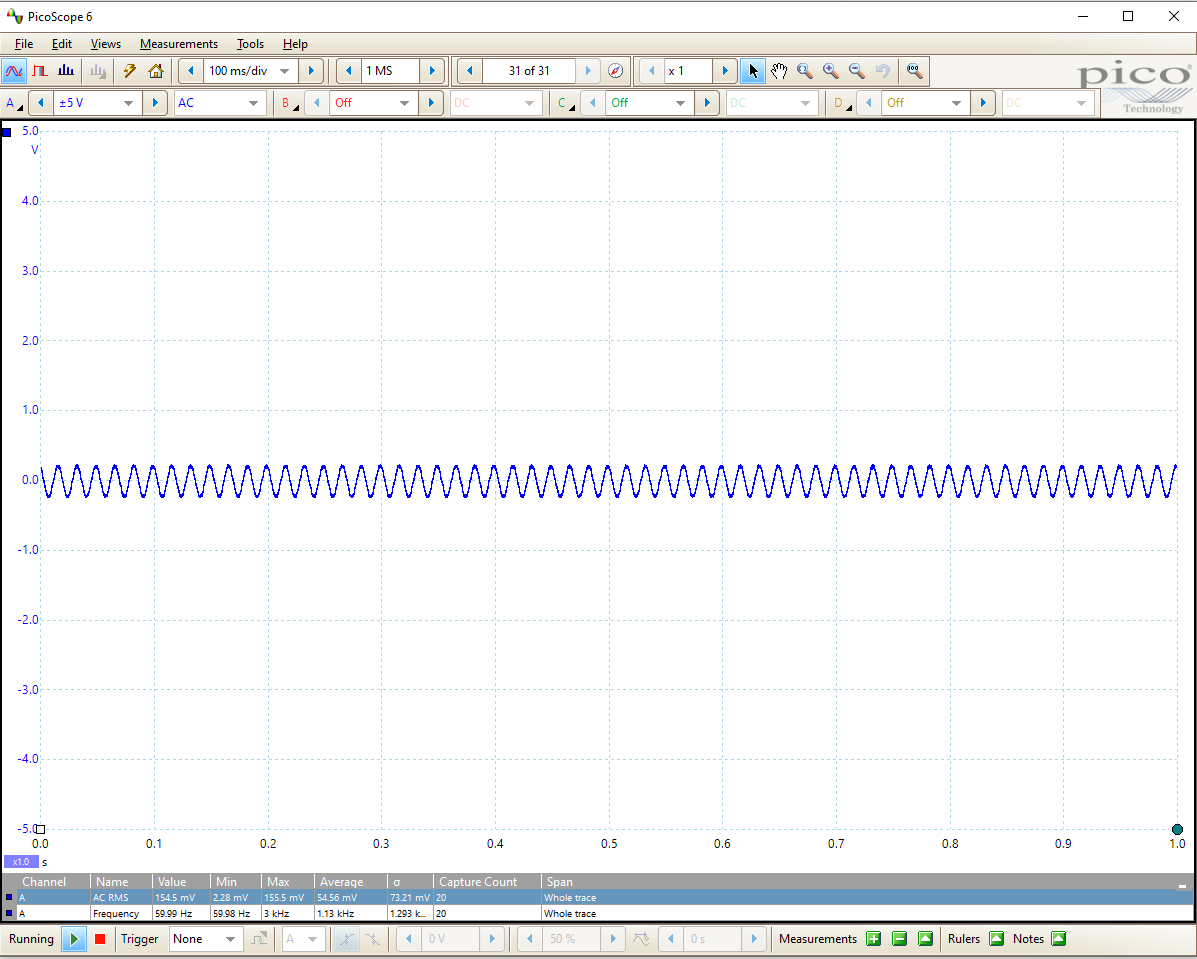
Test one light bulb – the current is around 2Amp and device reads around 2Amp as well ( i modified the calibration value).
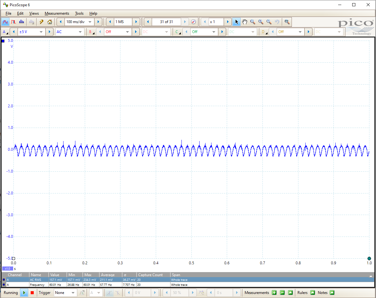
when i change the load to a heater which consumes somewhere around 15A, the device reads 10-11Amp.
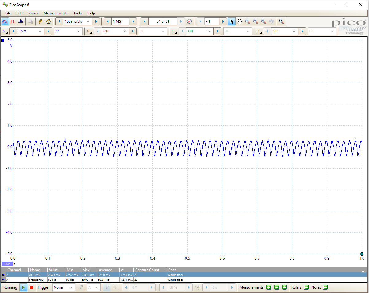
now i change the load to 70Amp load and the CT reads somewhere around 33-35Amp.
I have. Read up in a decent electrical engineering text book about c.t. theory, and consider how the various losses change in relation to each other as the flux in the core changes.
What does the spec. sheet for your c.t. say about the operating range?
That is pure advertising hype. I don’t believe that it will maintain the stated accuracy down to zero - as indeed you have shown. As I implied, it is inherent in the way that all current transformers work that the inaccuracies increase at low currents.
You need to find a data sheet that gives the full specification, including the band over which the claimed accuracy is maintained.
its defiantly understandable that it wont be highly accurate at low current. but in my case the main issue is that the readings are not linear. if i calibrate at point A. it will read great there but if i go above an billow that readings change drastically.
I have a different CT which has 0-100A range and coil rations is 1000/ and its outputting linear.
i cant seem to think of anything which can cause this non linearity. any insights will be appreciated.
Can you explain that sentence? How are you differentiating between linearity and accuracy? If you set the calibration at rated current, at what current does the ratio of output current to input current deviate by (say) 1%, 5%, 10%, etc?
What you have appears to be a relatively inexpensive c.t., and disturbingly it appears to be available only from factors and there appears to be no original and credible data sheet. So I’m not at all surprised that you see a large error at 1% rated current.
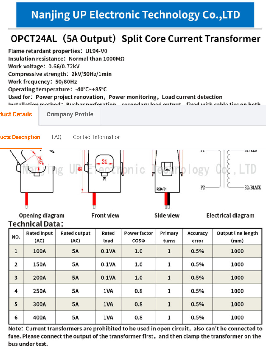
I should perhaps refer you to a US manufacturer of quality c.t’s. The Magnelab SCT-0750-200 has a linearity of ±1% over the range 10% – 130% of rated current, with a phase error of less than 2° at currents above 70 A. That is listed at $48 by Aim Dynamics.
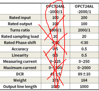
If that’s the case, it is not a 2000:1 c.t as Wayne asserts, but 10 kA : 5 A, which I don’t believe could be expected to be sold on the retail market. And a c.t. to fit on 10 kA busbars would be quite large.
A lot of things don’t add up. From the original data, it appears in fact to be a 200 A : 100 mA device, and an 11 Ω burden is not ridiculous if he’s got an emonPi or Arduino.
It appears Wayne has an $8 Chinese c.t. I wouldn’t like to say very much more about it. The accuracy claims are probably - shall we say - speculation, maybe the 0.5% is correct at rated current, but over what range each side of that?
i guess now we know that its a Chinese CT. lets see if someone can point to the right direction.
i did confirm with the manufacture and they did clarify that its 200A:100mA CT.
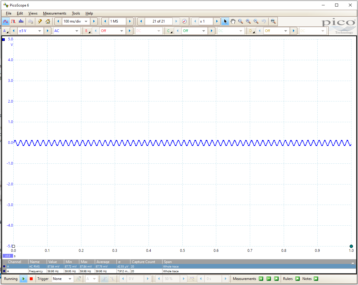
i connected to scope and here are some results ( used 11ohm resistor across CT sec coil).
It’s quite hard to distinguish anything about the waveform from those pictures, but only the first two look as if the waveform is correct. Above that, the negative part looks a bit ‘peaky’ - but it’s hard to tell. Is the current waveform itself a clean sine wave?
However, if the table Bill found is correct, at 0.1 VA rating, then it should be not quite OK at rated current when driving 100 mA into 11 Ω (0.11 VA), but it should be OK below that. A 10 Ω burden should be good to the rated current. You’re nowhere near rated current, so I wouldn’t expect a problem in that area until you get close to 200 A.
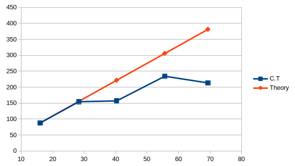
Plotting the numbers in those pictures, I get this:
If you have a DMM capable of reading to 100 mA, try that instead of your Picoscope and the burden resistor (i.e. drive the c.t. straight into the current input of the meter).