Although dating from 2004, it is a very comprehensive document ranging from a description of the principles of the 1-Wire network and transmission line theory to recommendations for the cable types and use of individual wires within cables.
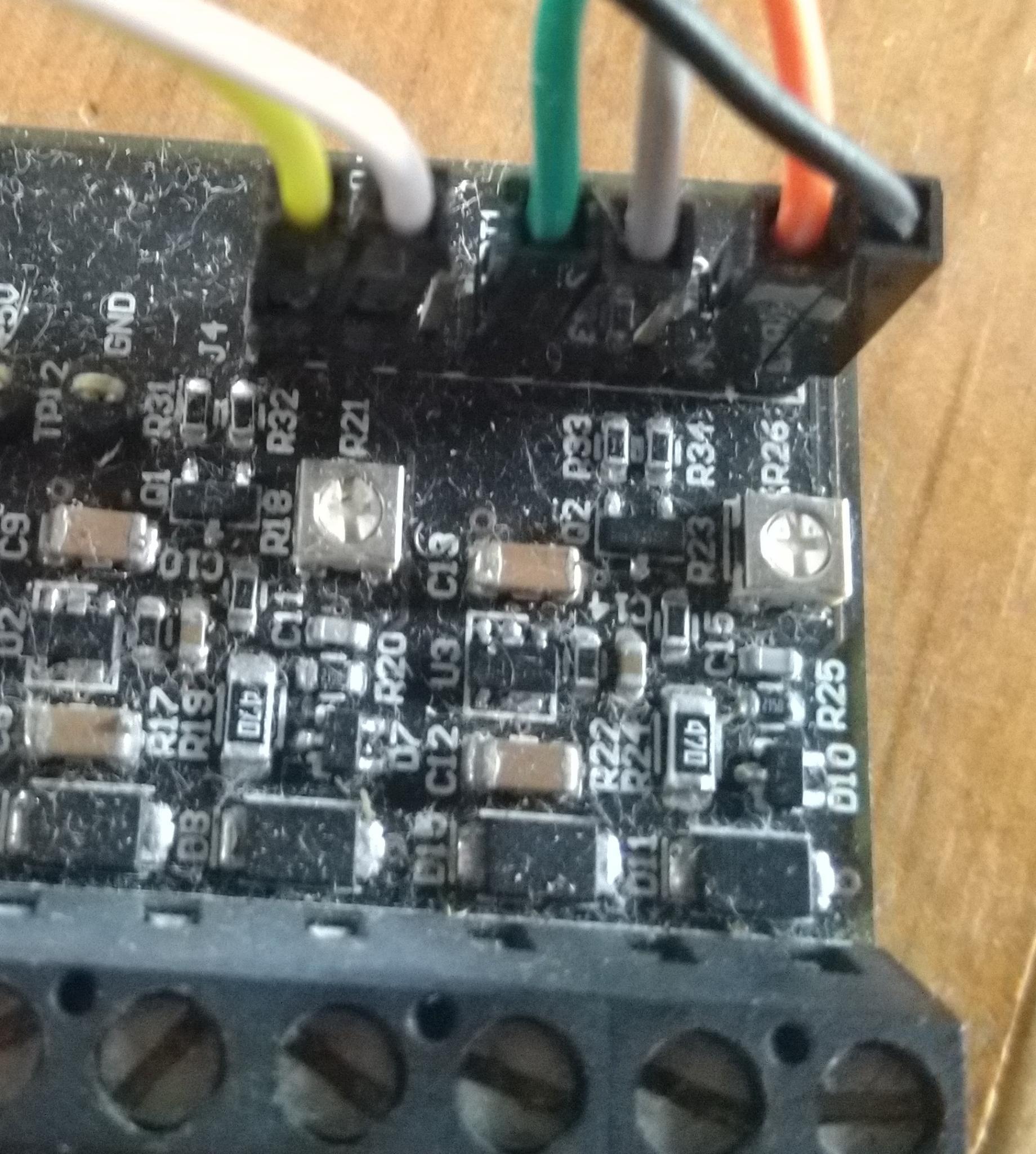
Hi, Thanks for the link. I was having trouble with my two outside sensors on my ASHP connected via a Cat 6 cable coming off the breakout board having regular drop outs of the temp reading and upsetting others directly connected to the board. A 100 Ohm resistor in series with the signal wire at the breakout board for the two outside sensors resolved the problem.
This sounds very much like reflections in the data line and a long ( ? ) cable to the external sensors would be the cause of your problem, and the series resistor is enough to dampen them sufficiently. Were the two on the a single cable in “daisy-chain”, with the others connected in “star” at the breakout board?
Sadly, it looks as if the document has been taken down, here’s my copy for anyone who needs it: 1-Wire-Design Guide v1.0.pdf (1.5 MB)
Hi Robert, The two on the single cable were using separate wires in the cat 6 cable while the other 4 were connected in a star arrangement at the breakout. I think I must have found the doc you referenced elsewhere and assumed it was on this forum. Thanks for providing it again. My cat 6 cable is about 8m long so not terribly long. I didn’t experiment with resistor values but since putting these in the readbacks have been completely reliable.
Thanks again,
Simon
How is your understanding of transmission line theory? The wires forming the bus are a transmission line. The data pulses travelling along, when they come to the end, will be completely absorbed if they see a resistance (impedance really) that exactly matches the impedance of the line. Anything else, and the pulse gets reflected. Both an open circuit and a short circuit will reflect the pulse equally well, and with pulses travelling up and down and meeting one another coming back, the data is rapidly garbled.
The resistors provide a bit of loss to absorb the reflections and so damp them down.
My training is in physics and have worked with in vacuum transmission lines for the position detection of charged particles in a spectrometer application. I think I have probably assumed these data signals are much “slower” than the pulses I have been used to dealing with and so the effects of reflections at impedance discontinuities can be neglected but it looks like not! Probably need resistors at each end of the line?
As usual, the manufacturer’s data sheet and application notes are by far the best sources.
If you look at the application note that Bill has linked to, I think there’s an assumption that the Master is a Maxim device with the proper terminating resistance. This won’t be the case when using a '328P processor, so experimentation might be needed; and, if you have access to the instrumentation, measurements on the bus will be very revealing.
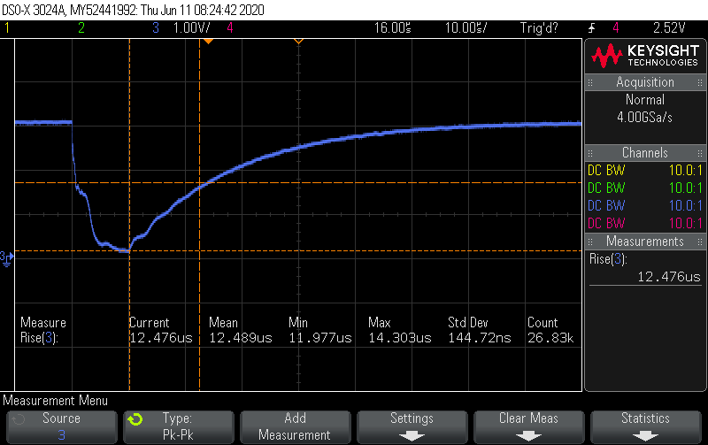
That 100R is the ideal total source impedance but some of that will be provided by the processor pin. I did some extreme 1wire testing last year with a little test board with trimpot that let me hunt the best value for my cpu pin (an stm32 uart pin). I landed on 68R, but that’s not necessarily indicative of what the AVR would need.
That Blue trace is the near end of the 1wire bus. The goal is to position that shelf on the initial falling edge so that it’s mid-way between high and low, and tweaking the pot moves it up and down. Then you can measure the pot and use that R value in your final design… 68R in my case.
On a much shorter bus, you probably won’t even see the reflection/shelf…
You are correct that the pulses themselves are too slow to have significant reflections (looks like 1-Wire is <=90kbps). However, the slew rate—the rate at which the signal rises or falls—is much higher. Adding a resistor also limits the slew rate, which reduces ringing.
I don’t think that’s quite correct. The frequency (ie repitition rate) of a signal has nothing to do with reflections. The only two factors are the rise/fall time (ie slew rate) and the impedance mismatch.
The impedance mismatch alone determines the amplitude of the ringing. The slew-rate effectively determines whether you need to treat the circuit as a lumped load or a transmission line. As the slew rate increases, the length at which a line needs to be treated as a transmission line (ie have source and load match the characteristic impedance of the line) shortens. For slow edges or short lines the connection can be treated as a lumped load (ie simple RC) and reflections can be ignored.
In 1-wire we have relatively slow edges hence we need very long lines to see the effect of the reflection. For a 1-wire length of only 10m say, you could ignore it.