Interesting shortcut.
A safe assumption would be to say the incoming value will be half 4096, because everything revolves around our bias.
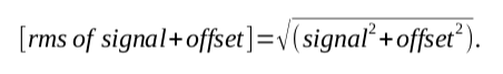
I guess this is the long way of working out how many bits are needed:
Around 16150 samples per CT channel are being made over 2.5 seconds.
16150 * 2048 = 33,075,200
squared accumulator 16150 * 2048 * 2048 = 67,738,009,600
uint32 2^32 = 4,294,967,296
uint64 2^64 = 1.844674407 x 10^19
I’ve looked at these numbers before, it’s sinking in a bit more now, I know what you mean by Massive.
It follows that the summing accumulators can be uint32 and the sqauring accummulator can be uint64. The squaring acc. is miles away from the maximum uint64.
Accumulation is being done in integer at the moment.
The accumulators are cast to floats every 2.5s, although originally doubles in Trystan’s code I switched to floats thinking to make use of the FPU, although I don’t know how to use it or if the compiler automatically makes use of it. Is it automatic? I’ve looked into using arm_math.h and have had some advice on integrating it, although hadn’t tried yet. The sqrtf function I’m using now also.
If the errors are that bad with floats then switching back to doubles will be necessary then. Despite the performance dip, which I’ve also noticed, the floats were chomped through much faster.
Edit: squared accumulator calculation. my shortcutting didn’t work, again.
/**
  ******************************************************************************
  * @file           : main.c
  * @brief          : Main program body
  ******************************************************************************
  ** This notice applies to any and all portions of this file
  * that are not between comment pairs USER CODE BEGIN and
  * USER CODE END. Other portions of this file, whether
  * inserted by the user or by software development tools
  * are owned by their respective copyright owners.
  *
  * COPYRIGHT(c) 2019 STMicroelectronics
  *
  * Redistribution and use in source and binary forms, with or without modification,
  * are permitted provided that the following conditions are met:
  *   1. Redistributions of source code must retain the above copyright notice,
  *      this list of conditions and the following disclaimer.
  *   2. Redistributions in binary form must reproduce the above copyright notice,
  *      this list of conditions and the following disclaimer in the documentation
  *      and/or other materials provided with the distribution.
  *   3. Neither the name of STMicroelectronics nor the names of its contributors
  *      may be used to endorse or promote products derived from this software
  *      without specific prior written permission.
  *
  * THIS SOFTWARE IS PROVIDED BY THE COPYRIGHT HOLDERS AND CONTRIBUTORS "AS IS"
  * AND ANY EXPRESS OR IMPLIED WARRANTIES, INCLUDING, BUT NOT LIMITED TO, THE
  * IMPLIED WARRANTIES OF MERCHANTABILITY AND FITNESS FOR A PARTICULAR PURPOSE ARE
  * DISCLAIMED. IN NO EVENT SHALL THE COPYRIGHT HOLDER OR CONTRIBUTORS BE LIABLE
  * FOR ANY DIRECT, INDIRECT, INCIDENTAL, SPECIAL, EXEMPLARY, OR CONSEQUENTIAL
  * DAMAGES (INCLUDING, BUT NOT LIMITED TO, PROCUREMENT OF SUBSTITUTE GOODS OR
  * SERVICES; LOSS OF USE, DATA, OR PROFITS; OR BUSINESS INTERRUPTION) HOWEVER
  * CAUSED AND ON ANY THEORY OF LIABILITY, WHETHER IN CONTRACT, STRICT LIABILITY,
  * OR TORT (INCLUDING NEGLIGENCE OR OTHERWISE) ARISING IN ANY WAY OUT OF THE USE
  * OF THIS SOFTWARE, EVEN IF ADVISED OF THE POSSIBILITY OF SUCH DAMAGE.
  *
  ******************************************************************************
  */
/* Includes ------------------------------------------------------------------*/
#include "main.h"
#include "stm32f3xx_hal.h"
#include "adc.h"
#include "dma.h"
#include "opamp.h"
#include "tim.h"
#include "usart.h"
#include "gpio.h"

/* USER CODE BEGIN Includes */
#define ARM_MATH_CM4
#include "arm_math.h"
#include "ds18b20.h"
#include <math.h>
#include <string.h>
typedef float float32_t;
/* USER CODE END Includes */

/* Private variables ---------------------------------------------------------*/

/* USER CODE BEGIN PV */
/* Private variables ---------------------------------------------------------*/

#define true 1
#define false 0
#define MID_ADC_READING 2000

// Serial output buffer
char log_buffer[150];

// Flag
uint8_t readings_ready = false;

// Calibration
const float VOLTS_PER_DIV = (3.3 / 4096.0);
float VCAL = 268.97;
float ICAL = 90.9;

// ISR accumulators
typedef struct channel_
{
  uint64_t sum_V_sq;
  uint64_t sum_I_sq;
  uint32_t sum_V;
  uint32_t sum_I;
  uint32_t sum_P;
  uint32_t count;

  uint8_t positive_V;
  uint8_t last_positive_V;
  uint8_t cycles;
} channel_t;

uint32_t pulseCount = 0;

//#define CTn 9 // number of CT channels
static channel_t channels[CTn];
static channel_t channels_copy[CTn];

/* USER CODE END PV */

/* Private function prototypes -----------------------------------------------*/
void SystemClock_Config(void);

/* USER CODE BEGIN PFP */
/* Private function prototypes -----------------------------------------------*/
//#define ARM_MATH_CM4
//#include "arm_math.h"
/* USER CODE END PFP */

/* USER CODE BEGIN 0 */
void process_frame(uint16_t offset)
{
  int32_t sample_V, sample_I, signed_V, signed_I;

  HAL_GPIO_WritePin(GPIOD, GPIO_PIN_8, GPIO_PIN_SET);
  for (int i = 0; i < adc_buff_half_size; i += CTn)
  {
    // Cycle through channels
    for (int ch = 0; ch < CTn; ch++)
    {
      channel_t *channel = &channels[ch];

      // ----------------------------------------
      // Voltage
      //float32_t theresult;
      //arm_rms_f32(float* adc1_dma_buff, uint32_t* sizeof(adc1_dma_buff), float* theresult);
      sample_V = adc1_dma_buff[offset + i + ch];
      signed_V = sample_V - MID_ADC_READING;
      channel->sum_V += signed_V;
      channel->sum_V_sq += signed_V * signed_V;
      // ----------------------------------------
      // Current
      sample_I = adc3_dma_buff[offset + i + ch];
      signed_I = sample_I - MID_ADC_READING;
      channel->sum_I += signed_I;
      channel->sum_I_sq += signed_I * signed_I;
      // ----------------------------------------
      // Power
      channel->sum_P += signed_V * signed_I;

      channel->count++;

      // Zero crossing detection
      channel->last_positive_V = channel->positive_V;
      if (signed_V > 0)
        channel->positive_V = true;
      else
        channel->positive_V = false;
      if (!channel->last_positive_V && channel->positive_V)
        channel->cycles++;

      // 125 cycles or 2.5 seconds
      if (channel->cycles >= 125)
      {
        channel->cycles = 0;

        channel_t *chn = &channels_copy[ch];
        // Copy accumulators for use in main loop
        memcpy((void *)chn, (void *)channel, sizeof(channel_t));
        // Reset accumulators to zero ready for next set of measurements
        memset((void *)channel, 0, sizeof(channel_t));

        if (ch == (CTn - 1))
        {
          readings_ready = true;
          /*
          sprintf(log_buffer, "chn->sum_V_sq:%lld\r\n", chn->sum_V_sq);
          debug_printf(log_buffer);
          sprintf(log_buffer, "chn->sum_I_sq:%lld\r\n", chn->sum_I_sq);
          debug_printf(log_buffer);
          sprintf(log_buffer, "chn->sum_V:%lld\r\n", chn->sum_V);
          debug_printf(log_buffer);
          sprintf(log_buffer, "chn->sum_I:%lld\r\n", chn->sum_I);
          debug_printf(log_buffer);
          sprintf(log_buffer, "chn->sum_P:%lld\r\n", chn->sum_P);
          debug_printf(log_buffer);
          sprintf(log_buffer, "chn->count:%ld\r\n", chn->count);
          debug_printf(log_buffer);
          sprintf(log_buffer, "chn->positive_V:%d\r\n", chn->positive_V);
          debug_printf(log_buffer);
          sprintf(log_buffer, "chn->last_positive_V:%d\r\n", chn->last_positive_V);
          debug_printf(log_buffer);
          sprintf(log_buffer, "chn->cycles:%d\r\n", chn->cycles);
          debug_printf(log_buffer);

            uint32_t sum_V_sq;
            uint32_t sum_I_sq;
            int32_t sum_V;
            int32_t sum_I;
            int32_t sum_P;
            uint32_t count;

            uint8_t positive_V;
            uint8_t last_positive_V;
            uint8_t cycles;
            */
        }
      }
    }
  }
  HAL_GPIO_WritePin(GPIOD, GPIO_PIN_8, GPIO_PIN_RESET);
}

/* USER CODE END 0 */

/**
  * @brief  The application entry point.
  *
  * @retval None
  */
int main(void)
{
  /* USER CODE BEGIN 1 */
  float V_RATIO = VCAL * VOLTS_PER_DIV;
  float I_RATIO = ICAL * VOLTS_PER_DIV;
  /* USER CODE END 1 */

  /* MCU Configuration----------------------------------------------------------*/

  /* Reset of all peripherals, Initializes the Flash interface and the Systick. */
  HAL_Init();

  /* USER CODE BEGIN Init */

  /* USER CODE END Init */

  /* Configure the system clock */
  SystemClock_Config();

  /* USER CODE BEGIN SysInit */

  /* USER CODE END SysInit */

  /* Initialize all configured peripherals */
  MX_GPIO_Init();
  MX_DMA_Init();
  MX_ADC3_Init();
  MX_ADC1_Init();
  MX_TIM8_Init();
  MX_USART2_UART_Init();
  MX_OPAMP4_Init();
  /* USER CODE BEGIN 2 */
  debug_printf("start\r\n");

  HAL_ADCEx_Calibration_Start(&hadc1, ADC_SINGLE_ENDED);
  HAL_ADCEx_Calibration_Start(&hadc3, ADC_SINGLE_ENDED);

  HAL_OPAMP_Start(&hopamp4);

  start_ADCs();

  /* USER CODE END 2 */

  /* Infinite loop */
  /* USER CODE BEGIN WHILE */
  while (1)
  {
    /*
    if (adc1_half_conv_complete && !adc1_half_conv_overrun)
    {
      adc1_half_conv_complete = false;
      process_frame(0);
    }

    if (adc1_full_conv_complete && !adc1_full_conv_overrun)
    {
      adc1_full_conv_complete = false;
      process_frame(adc_buff_half_size);
    }
*/
    if (readings_ready)
    {
      readings_ready = false;
      //process_ds18b20s();

      for (int ch = 0; ch < CTn; ch++)
      {
        channel_t *chn = &channels_copy[ch];

        float Vmean = (float)chn->sum_V / (float)chn->count;
        float Imean = (float)chn->sum_I / (float)chn->count;

        float f32sum_V_sq_avg = (float)chn->sum_V_sq / (float)chn->count;
        f32sum_V_sq_avg -= (Vmean * Vmean); // offset removal

        float f32sum_I_sq_avg = (float)chn->sum_I_sq / (float)chn->count;
        f32sum_I_sq_avg -= (Imean * Imean); // offset removal

        if (f32sum_V_sq_avg < 0) // if offset removal cause a negative number,
          f32sum_V_sq_avg = 0;   // make it 0 to avoid a nan at sqrt.
        if (f32sum_I_sq_avg < 0)
          f32sum_I_sq_avg = 0;

        float Vrms = V_RATIO * sqrtf(f32sum_V_sq_avg);
        float Irms = I_RATIO * sqrtf(f32sum_I_sq_avg);

        //float* sqrtV_temp;
        //float* sqrtI_temp;
        //arm_sqrt_f32(f32sum_V_sq_avg, sqrtV_temp);
        //arm_sqrt_f32(f32sum_I_sq_avg, sqrtI_temp);
        //float Vrms = V_RATIO * *sqrtV_temp;
        //float Irms = I_RATIO * *sqrtI_temp;

        float f32_sum_P_avg = (float)chn->sum_P / (float)chn->count;
        float mean_P = f32_sum_P_avg - (Vmean * Imean); // offset removal
        float realPower = V_RATIO * I_RATIO * mean_P;

        float apparentPower = Vrms * Irms;

        float powerFactor;
        // calculate PF, preventing dividing by zero error.
        if (apparentPower != 0)
        {
          powerFactor = realPower / apparentPower;
        }
        else
          powerFactor = 0;

        sprintf(log_buffer, "V%d:%.2f,I%d:%.3f,RP%d:%.1f,AP%d:%.1f,PF%d:%.3f,C%d:%ld,", ch, Vrms, ch, Irms, ch, realPower, ch, apparentPower, ch, powerFactor, ch, chn->count);
        debug_printf(log_buffer);

        uint32_t current_millis = HAL_GetTick();
        sprintf(log_buffer, "millis:%ld\r\n", current_millis);
        debug_printf(log_buffer);

        //ref_rms_f32();
        //sprintf(log_buffer,"\r\n");
        //debug_printf(log_buffer);


      }
      sprintf(log_buffer, "PC:%ld\r\n", pulseCount);
        debug_printf(log_buffer);
    }

    /*
    if (readings_ready)
    {
      readings_ready = false;

      for (int n = 0; n < CTn; n++)
      {
        channel_t *chn = &channels_copy[n];

        float Vmean = chn->sum_V * (1.0 / chn->count);
        float Imean = chn->sum_I * (1.0 / chn->count);

        chn->sum_V_sq *= (1.0 / chn->count);
        chn->sum_V_sq -= (Vmean * Vmean);
        float Vrms = V_RATIO * sqrt((float)chn->sum_V_sq);

        chn->sum_I_sq *= (1.0 / chn->count);
        chn->sum_I_sq -= (Imean * Imean);
        float Irms = I_RATIO * sqrt((float)chn->sum_I_sq);

        float mean_P = (chn->sum_P * (1.0 / chn->count)) - (Vmean * Imean);
        float realPower = V_RATIO * I_RATIO * mean_P;

        float apparentPower = Vrms * Irms;
        float powerFactor = realPower / apparentPower;

        sprintf(log_buffer, "V%d:%.2f,I%d:%.3f,RP%d:%.1f,AP%d:%.1f,PF%d:%.3f,C%d:%ld,", n, Vrms, n, Irms, n, realPower, n, apparentPower, n, powerFactor, n, chn->count);
        debug_printf(log_buffer);

        uint32_t current_millis = HAL_GetTick();
        sprintf(log_buffer, "millis:%ld\r\n", current_millis);
        debug_printf(log_buffer);
        //debug_printf("\r\n");
      }

      //ref_rms_f32();
      //sprintf(log_buffer,"\r\n");
      //debug_printf(log_buffer);

      sprintf(log_buffer, "PC:%ld\r\n", pulseCount);
      debug_printf(log_buffer);
    }
    */
    /* USER CODE END WHILE */

    /* USER CODE BEGIN 3 */
  }
  /* USER CODE END 3 */
}

/**
  * @brief System Clock Configuration
  * @retval None
  */
void SystemClock_Config(void)
{

  RCC_OscInitTypeDef RCC_OscInitStruct;
  RCC_ClkInitTypeDef RCC_ClkInitStruct;
  RCC_PeriphCLKInitTypeDef PeriphClkInit;

  /**Initializes the CPU, AHB and APB busses clocks
    */
  RCC_OscInitStruct.OscillatorType = RCC_OSCILLATORTYPE_HSE;
  RCC_OscInitStruct.HSEState = RCC_HSE_ON;
  RCC_OscInitStruct.HSEPredivValue = RCC_HSE_PREDIV_DIV1;
  RCC_OscInitStruct.HSIState = RCC_HSI_ON;
  RCC_OscInitStruct.PLL.PLLState = RCC_PLL_ON;
  RCC_OscInitStruct.PLL.PLLSource = RCC_PLLSOURCE_HSE;
  RCC_OscInitStruct.PLL.PLLMUL = RCC_PLL_MUL9;
  if (HAL_RCC_OscConfig(&RCC_OscInitStruct) != HAL_OK)
  {
    _Error_Handler(__FILE__, __LINE__);
  }

  /**Initializes the CPU, AHB and APB busses clocks
    */
  RCC_ClkInitStruct.ClockType = RCC_CLOCKTYPE_HCLK | RCC_CLOCKTYPE_SYSCLK | RCC_CLOCKTYPE_PCLK1 | RCC_CLOCKTYPE_PCLK2;
  RCC_ClkInitStruct.SYSCLKSource = RCC_SYSCLKSOURCE_PLLCLK;
  RCC_ClkInitStruct.AHBCLKDivider = RCC_SYSCLK_DIV1;
  RCC_ClkInitStruct.APB1CLKDivider = RCC_HCLK_DIV2;
  RCC_ClkInitStruct.APB2CLKDivider = RCC_HCLK_DIV1;

  if (HAL_RCC_ClockConfig(&RCC_ClkInitStruct, FLASH_LATENCY_2) != HAL_OK)
  {
    _Error_Handler(__FILE__, __LINE__);
  }

  PeriphClkInit.PeriphClockSelection = RCC_PERIPHCLK_USART2 | RCC_PERIPHCLK_TIM8;
  PeriphClkInit.Usart2ClockSelection = RCC_USART2CLKSOURCE_SYSCLK;
  PeriphClkInit.Tim8ClockSelection = RCC_TIM8CLK_HCLK;
  if (HAL_RCCEx_PeriphCLKConfig(&PeriphClkInit) != HAL_OK)
  {
    _Error_Handler(__FILE__, __LINE__);
  }

  /**Configure the Systick interrupt time
    */
  HAL_SYSTICK_Config(HAL_RCC_GetHCLKFreq() / 1000);

  /**Configure the Systick
    */
  HAL_SYSTICK_CLKSourceConfig(SYSTICK_CLKSOURCE_HCLK);

  /* SysTick_IRQn interrupt configuration */
  HAL_NVIC_SetPriority(SysTick_IRQn, 0, 0);
}

/* USER CODE BEGIN 4 */

void onPulse()
{
  pulseCount++;
}

/* USER CODE END 4 */

/**
  * @brief  This function is executed in case of error occurrence.
  * @param  file: The file name as string.
  * @param  line: The line in file as a number.
  * @retval None
  */
void _Error_Handler(char *file, int line)
{
  /* USER CODE BEGIN Error_Handler_Debug */
  /* User can add his own implementation to report the HAL error return state */
  while (1)
  {
  }
  /* USER CODE END Error_Handler_Debug */
}

#ifdef USE_FULL_ASSERT
/**
  * @brief  Reports the name of the source file and the source line number
  *         where the assert_param error has occurred.
  * @param  file: pointer to the source file name
  * @param  line: assert_param error line source number
  * @retval None
  */
void assert_failed(uint8_t *file, uint32_t line)
{
  /* USER CODE BEGIN 6 */
  /* User can add his own implementation to report the file name and line number,
     tex: printf("Wrong parameters value: file %s on line %d\r\n", file, line) */
  /* USER CODE END 6 */
}
#endif /* USE_FULL_ASSERT */

/**
  * @}
  */

/**
  * @}
  */

/************************ (C) COPYRIGHT STMicroelectronics *****END OF FILE****/