Ah, had not realised that - thanks.
Can’t remember if the timestamp is window start or window end?
Ah, had not realised that - thanks.
Can’t remember if the timestamp is window start or window end?
Thanks all (back at work today and have only just sat down to catch up). I’ll continue to tinker with the values and will read up on emoncms. Its been running for almost 24h, I don’t appear to have any errors in the feed data being sent and the feeds look healthy (green) at the emoncms end.
The integrations are way way off (I appreciate I’ve still got some callibration to do at the arduino end as I’ve got deltas between the apparent and real power at lower current draws.
Thanks again.
Presumably at very low currents?
That’s because all c.t’s are inherently inaccurate at low currents, “low” being relative to the rated current and a function of cost. I have plans to do something about it, but there’s no timescale.
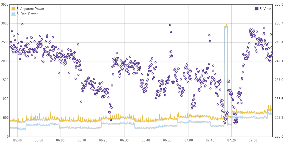
Define very low currents…the household’s quiescent power usage was measured on an old energy monitor to be approx 300W (fridges).
According to the emoncms. apparent and real respectively, are approx. 430W and 250W (UK Voltage). Not properly read up about it but I’d assumed low current to be less than that - I’ve not tweaked the power coefficient yet, just the voltage and current.
During lockdown, with no kW draw devices, a crude energy monitor would show around 500 - 600W avg if the boys have their PCs on. Increases to 750W avg during the evening with TV / lights etc… Maximum draw in a day could be 9 - 12kW, say if there was one shower and a dryer on, 20kW if both showers and the dryer were on.
Define what you’re prepared to spend for a higher quality c.t. ![]() 300 W is pushing your luck with a cheap (= YHDC SCT-013-00) 100 A c.t., accuracy is only specified above 10 A for that particular model.
300 W is pushing your luck with a cheap (= YHDC SCT-013-00) 100 A c.t., accuracy is only specified above 10 A for that particular model.
I think you probably need to go through the full calibration procedure, and if you’re really interested in matching your meter reads, then be prepared to do very fine tweaks to the calibration until you get it “close enough” over an extended period of time (a few weeks). Otherwise, calibrate at around the current that you’re concerned about, but be prepared for the 10 - 20 kW loads to be wrong.
If you look at the c.t. test report in ‘Learn’, you’ll see how the phase error rockets up as the current drops. That’s what is causing most of the trouble.
Everyday’s a school day and I’m at the bottom of a steep learning curve. Had read that test report, admittedly I’d focussed on the first part.
That was the plan re: the full calibration - I’ll keep tweaking for a long while yet, both the calibration, the software and probably the hardware too. I wouldn’t be surprised if I end up learning that I need multiple current sensors, each with specific ranges of accuracy and the emonpi decides which sensor to use based on the current being measured 
I would (be surprised), because how are you going to switch the primary current between them? Each c.t has a maximum current rating, above which saturation occurs, and that can lead to overheating. Manufacturers always recommend using the c.t. that has the lowest rated current which is more than the maximum that it will see in service. Quite honestly, I’d describe that idea as ‘hopeful’. You’d need a 100 A contactor, driven from your Arduino, to put a shunt circuit around each of the lowest-rated c.t’s, and the resistance of that loop - including the contacts when they get old and worn - would need to be less than the resistance of the conductor through the c.t., by a factor that was at least the ratio of the currents. I can’t see it being achievable.
Also bear in mind that it’s always safe to short-circuit a c.t., and you should do if its burden is disconnected. It might be safe to open-circuit it, but that depends on the integrity of a protection diode - even if one is fitted, which is not necessarily the case. The only type that it’s safe to leave open-circuit is the voltage-output type.