Setup 3-phase emonTX with emonESP using emoncms.org

Hello Peter, that looks like a very useful guide. I want to end up with exactly what you have done but in the UK - that is 3-phase, emontx-EmonESP-emoncms.org. I currently have the standard emontx 3.4 and shop supplied WiFi add on setup for single phase with 4x CTs. I discovered that this does not give correct results on 3-phase (see EmonTx Input labels - confused new user - #10 by borpin )
Is there some easy (ie lazy and needing very limited technical knowledge!) way to get my hardware loaded with the necessary firmware to operate correctly on 3-phase?

I can only say, use platformio at your own risk. I won’t be able to help you if you have problems with it.

Note there is a pre-compiled 9600 baud version of the ESP8266 sketch:

https://community.openenergymonitor.org/uploads/short-url/zegtvp5lICQT1w6J7ZoTXRnsiw3.bin

@Borpin says he uses Release 1.4.0 · esphome/esphome-flasher · GitHub to flash anything to ESP8266 devices.

1 Like

I appreciate you are trying to be helpful here Robert but each time I follow one of these links I end up somewhere where things are written in a language I’ve never seen before- it looks like English but I’ve no idea what it means.
I guess I’m just nowhere near qualified to be trying to use OEM offerings and I’m not really prepared to put the time in to learn this language.

I think I’d rather thought that from what you’d written in the other thread. I’ve been using computers for some years, starting with a remote mainframe running Fortran 4 and programming on punched paper tape - this was 40 years ago. I’ve come across a fair few operating systems, compilers and desktops in my time and never, ever, had something screw things up like platformio did. It took me a couple of hours to put everything back. I hate to think of the mess you’d be in if it did that to you.

If only for that reason, I advise you to stay with the tried and tested Arduino IDE.

FORTRAN, Algol, ICL 1900, IBM 1130 etc

That was 50 years ago for me - I hoped things had progressed!

I have followed all the steps and I am getting wrong data in ESP mini D1.
At the beggining I was using continous monitoring firmware + EmonESP 2.3 and everything works great.
Now I changed to

OpenEnergyMonitor.org
ct1:0.00,ct2:0.00,ct3:0.00,ct4:0.00,vrms:0.00,t1:23.75,t2:300.00,t3:300.00,t4:300.00,t5:300.00,t6:300.00,pulses:1
ct1:-0.00,ct2:-0.88,ct3:-1.75,ct4:0.00,vrms:0.65,t1:23.75,t2:300.00,t3:300.00,t4:300.00,t5:300.00,t6:300.00,pulses:1

I also modified this

Then I downloaded last EmonEsp and I changed the baudrate from 115200 to 9600.

And now I am getting:


Which is quite weird

In my MQTT broker I receiving this kind of data CT measures are in W and I expected Amps ( I have change the coils directions), voltage looks nice.


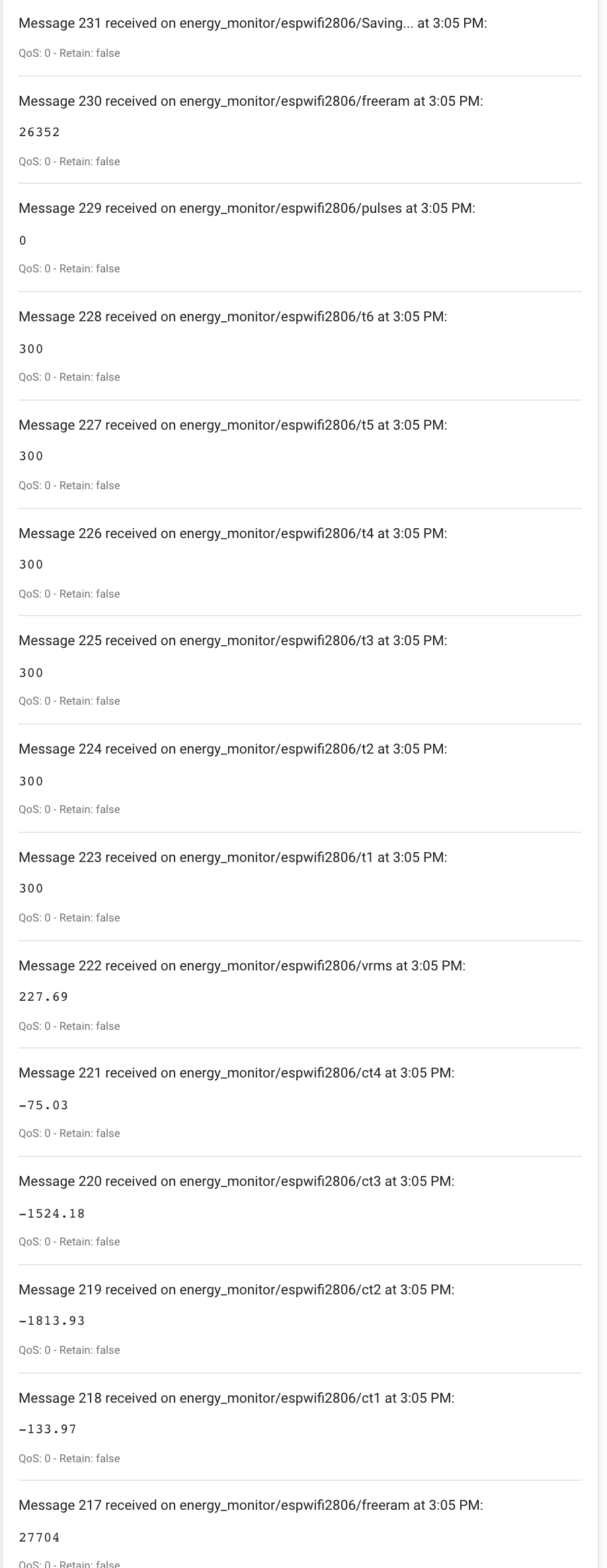
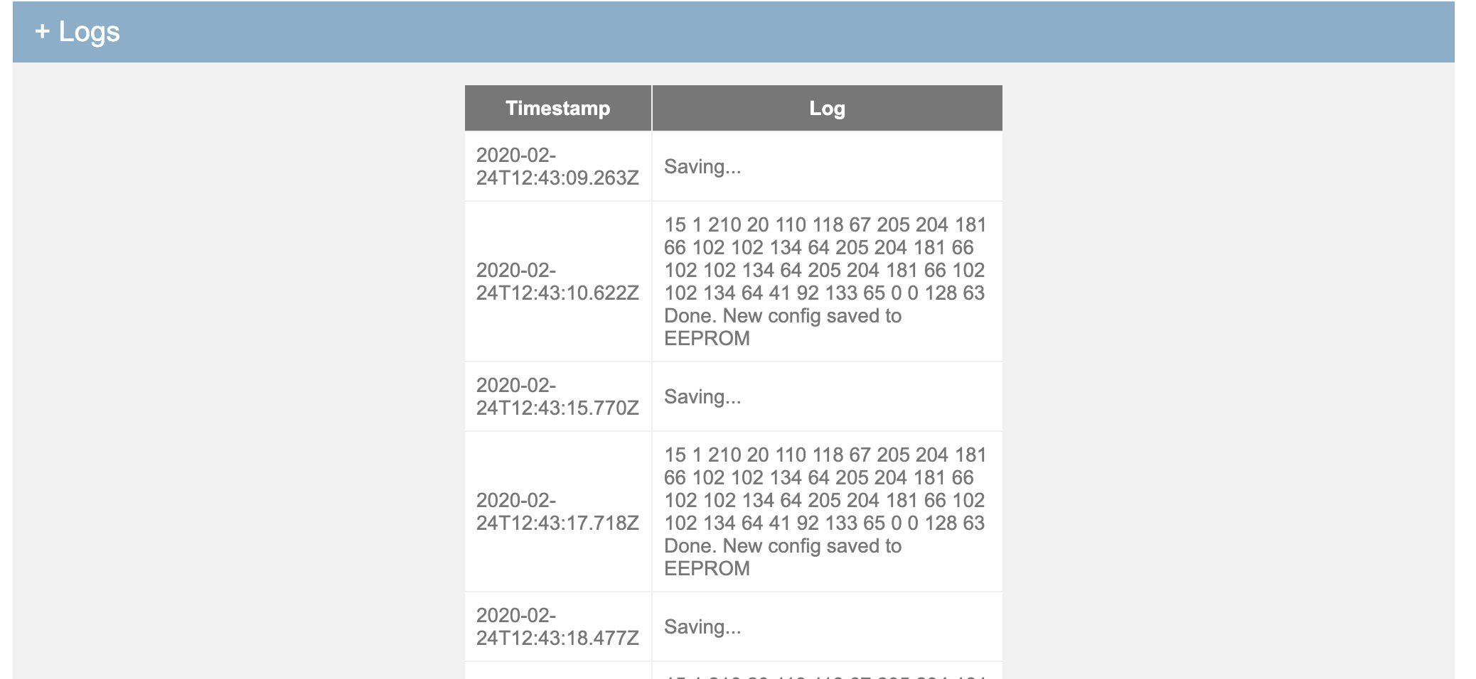
I dont have any temp probe connected so the are equal to 300. And then this extrange message Saving…
Any help is welcome I spent all the morning with this issue.
Best regards

As far as I am aware, the sketch as published in the forum here is correct and works (it reports V1.4, but it is really V1.6):

Any changes made by someone else, without referring it to me, are their responsibility.

OEM has always sent the output in watts. You can change the sketch if you wish, it is lines 942 - 951. The variables you want are I1rms, etc. But it means you will NOT know the real power, which is what you pay for, unless your send both power and current.

I’m afraid I don’t have an ESP8266, so I can’t investigate that side for you.

Thank you again, so probably my problem is in the EmonESP firmware cause I am using last release of emonTx_3phase

Looking at the data the ESP is getting - you have NOT edited the sketch to say you want the ESP output.

Read line 82 and all of the comment:

#define RFM69CW                                  // The type of Radio Module, or none.
                                                 // Can be RFM69CW 
                                                 //   or SERIALOUT if a wired serial connection is used 
                                                 //   or EMONESP if an ESP WiFi module is used (see https://github.com/openenergymonitor/
                                                 //     emonTxFirmware/blob/master/emonTxV3/noRF/emonTxV3_DirectSerial/emonTxV3_DirectSerial.ino) 
                                                 //   or don't define anything if neither radio nor serial connection is required - in which case 
                                                 //      the IDE serial monitor output will be for information and debugging only.
                                                 // The sketch will hang if the wrong radio module is specified, or if one is specified and not fitted.
                                                 // For all serial output, the maximum is 9600 baud. The emonESP module must be set to suit.

I think that the 3-phase sketch has the “EMONESP” well defined,
WhatsApp Image 2020-02-25 at 8.30.32 AM

I think that my issue is that my ESP thinks somehow that I want to change the EEPROM configuration.
Can be one of this 3 things
1- I am using esp8266mod core (same than huzza) mounted in a mini D1 dev board.
2- I also have a LCD mounted but I didn’t add the libraries yet, maybe any pin is HIGH and the board is understanding that it have to save any value in the EEPROM getting:

Got '15 1 210 20 110 118 67 205 204 181 66 102 102 134 64 205 204 181 66 102 102 134 64 205 204 181 66 102 102 134 64 41 92 133 65 0 0 128 63 Done. New config saved to EEPROM'
Got 'ct1:0.01,ct2:2.48,ct3:4.98,ct4:-0.00,vrms:3.36,t1:300.00,t2:300.00,t3:300.00,t4:300.00,t5:300.00,t6:300.00,pulses:0'
Got 'Saving...'
Got '15 1 210 20 110 118 67 205 204 181 66 102 102 134 64 205 204 181 66 102 102 134 64 205 204 181 66 102 102 134 64 41 92 133 65 0 0 128 63 Done. New config saved to EEPROM'

edit I saw this message comes from save_config() config.ino in emonTX side
edit2 Maybe the emonTX is taking the emonesp as confing input parameters

3- Something involved with the 3-PHASE firmware for emontx because with the last release of single phase continuous monitoring everything works well.

I am going to check these issues

Okey!! now work!!!
The trick was remove the getCalibration function in emonTx_3phase_PLL.ino

Last question, I would like more info in the payload:
can I modify this struct?
from

typedef struct { int power1, power2, power3, power4, Vrms, temp[MAXONEWIRE] = {UNUSED_TEMPERATURE,UNUSED_TEMPERATURE,
                  UNUSED_TEMPERATURE,UNUSED_TEMPERATURE,UNUSED_TEMPERATURE,UNUSED_TEMPERATURE};
                  unsigned long pulseCount; } PayloadTx; 

to

typedef struct {
    int Vrms,power1, power2, power3, power4; // W
    float powerFactor1, powerFactor2,powerFactor3,powerFactor4; // cosphi
    float Vrms, I1rms, I2rms, I3rms, I4rms; // Amps
    unsigned long sumPeriodSamples; // Wh
} PayloadTX;

Best regards and thanks for the support

edit I got it work adding to void sendResults()

   #if defined EMONESP && !defined SERIALOUT
    #if WIRES == 3-WIRE
    Serial.print(F("ct1:")); Serial.print(realPower1+realPower2);            // These for compatibility, but whatever you need if the receiver is configured to suit. 
    Serial.print(F(",ct2:0.0"));
    #else
    Serial.print(F("ct1:")); Serial.print(realPower1);
    Serial.print(F(",ct2:")); Serial.print(realPower2);
    #endif    
    Serial.print(F(",ct3:")); Serial.print(realPower3);
    Serial.print(F(",ct4:")); Serial.print(realPower4);
    Serial.print(F(",vrms:")); Serial.print(Vrms);
    Serial.print(F(",I1rms:")); Serial.print(I1rms);
    Serial.print(F(",I2rms:")); Serial.print(I2rms);
    Serial.print(F(",I3rms:")); Serial.print(I3rms);
    Serial.print(F(",I4rms:")); Serial.print(I4rms);
    Serial.print(F(",pf1:")); Serial.print(powerFactor1);
    Serial.print(F(",pf2:")); Serial.print(powerFactor2);
    Serial.print(F(",pf3:")); Serial.print(powerFactor3);
    Serial.print(F(",pf4:")); Serial.print(powerFactor4);

That is the correct place. “Payload” is only for the RFM radio.

1 Like

getCalibration does nothing and returns immediately unless there is serial input. The emonESP should NOT be sending anything back to the emonTx.
With getCalibration( ) removed, you will not be able to calibrate the sketch using the serial adapter and your Arduino IDE.

1 Like

Hello, first post here. Got my emontx v3.4 yesterday and spent a lot of time to make 3 phase reporting work with emonesp before finding this thread. I was able to compile both the emonesp and the emontx firmware with platformio, they already talk to each other, but for some reason, I’m unable to flash the emontx via the UART headers (I get this error message: avrdude: stk500_recv(): programmer is not respondingavrdude: stk500_getsync() attempt 1 of 10: not in sync: resp=0x00 and it continues until it reaches 10) so I had to flash via another Arduino using the ICSP headers. Anyone has an idea how to fix that? Perhaps a working bootloader for the emontx? I was searching through the github site but couldn’t find one (emonupload pulls a bootloader and I flashed that but it didn’t work - I also tried flashing an Uno bootloader from the Arduino IDE but that didn’t work either). I hope I don’t have to flash very often but not having to use ICSP for flashing would be a big advantage :slight_smile:

Welcome, Zolan, to the OEM forum.

Unfortunately, I can’t help you with platformio. I am only able to support you when you use the Arduino IDE.

The documentation that you downloaded along with the 3-phase sketch does tell you, on page 3, what you need to do to get it working with an ESP8266, so any problem there must be due to platformio.

avrdude: stk500_recv(): programmer is not responding is sadly a very general message and it just means that it cannot communicate. It could be the wrong port on your computer, or a cable, or a problem with your FTDI to USB programmer (some programmers do not use the RTS line, which would mean the emonTx did not get reset at the correct instant, so did not enter programming mode). You should not need to use ICSP, the emonTx came to you with a bootloader and a working sketch installed.

It could be the wrong port on your computer,

Or a data rate mismatch. e.g. 115200 bps is needed, but 38400 bps is selected.

No, that is automatically selected for programming mode. It is different to the data rate for serial communication done by the sketch.

Thanks both for the responses. I have tried it with the Arduino IDE and also with avrdude manually (even tried from a Mac besides my Linux box), but neither worked. My USB UART was successful in flashing the ESP, so I think the UART & cables are working fine - also, I was successful flashing the emontx via the UART earlier in the day but something must have happened that “killed” the UART. I was looking for a way to restore the thing to a factory default state (including the boot loader), do you know if that’s possible at all?
EDIT: Forgot to mention that I have had the same error message in each case.

Gotcha. :wink:

I don’t. Some of our sketches do come in binary form with the bootloader. If that is your problem, I would guess (I’m not an expert in this area) that loading one of those would then mean that you could use the FTDI port once more. There’s one on Github at emonTxFirmware → emonTxV3 → RFM → emonTxV3.4 → emonTxV3_4_DiscreteSampling → compiled

I don’t know that this will work, if it does, I think you will have the same bootloader that we use normally.