PZEM-016 single phase modbus energy meter

There seems to be quite a selection.
Here’s a direct connect 5A base, 65 A max 230V, 50 Hz unit for less than a tenner.

That one seems to only have an S0 pulse output not modbus/rs485, but yes there are many out there.

Reminds me of a song from the 50s… (Shake, Rattle and Roll)
I’m like a one-eyed cat peepin’ in a sea-food store

I’m not familiar with what they offer over their serial bus, and how those registers related to the IC registers, but certainly the IC claims to tally positive and negative energy separately. I suspect that “energy accumulation frequency” mentioned in the last paragraph below is what the energy diverter folk refer to as their “bucket”, i.e. how quickly it will note the change in direction and start tallying into the other register.

10.13.1. Energy Accumulation

In E1 path, positive and negative active powers are accumulated into the energy 
accumulators according to their signs; for example, positive active power is 
accumulated into PPCNT (0x10F0), and negative active power is accumulated into 
NPCNT (0x10F1). Besides, other data, such as I1 current RMS or a constant 
(preset in the register DATACP, 0x10FC), also can be selected to be accumulated 
into PPCNT via configuring bits PSEL1~PSEL0 (bit[1:0] of PMCtrl4, 0x287D) when 
the chip is used for low power applications.

In E2 path, positive and negative active/reactive powers are accumulated into 
the energy accumulators according to their signs; for example, positive power
is accumulated into PQCNT (0x10F6), and negative  power is accumulated 
into NQCNT (0x10F7).

When MTCLK frequency is 3.2768MHz, 1.6384MHz or 819.2kHz, the energy accumulation 
frequency is 12.8kHz. When MTCLK frequency is 32768Hz, the energy accumulation 
frequency is 2979Hz.

By way of comparison, here’s a pic I took from my ADE energy IC a few years back. The Red trace is current, which you can see switches from a low level forward current to a high level reverse current. The Yellow trace is the /IRQ signal coming out of the IC to alert me that energy flows have reversed. You can see it takes almost two full 50Hz line cycles to alert me. The IRQ is just informational as (like yours) it internally flips to the negative energy accumulator upon reversal, but I assume the IRQ is coincident with that flip and so gives an indication of how long it takes.

Nice review Paul!

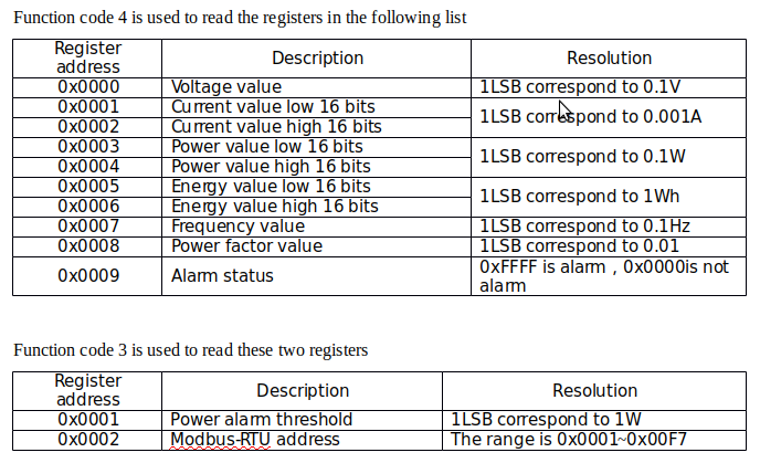
The PZEM-016 has a total of only 12 register addresses. Here’s the map:
pzem-016-registers
It would’ve been nice if they implemented the processor’s bi-directional functions on the 485 bus. :disappointed:

Could they be referring to the sample rate?

It could be both for energy / power given unity power factor, but if the power factor is not exactly 1, then there has to be some “opposite-direction” power over one mains cycle. I struggle with the meaning of accumulating energy and power over less than a cycle, with the intention of separating it into forward and reverse quantities.

The implication of considering less than a cycle is that for a pure reactive load, which does not consume power (i.e. there is no heating effect), the customer would be charged for absorbing power or consuming energy on alternate quarter-cycles, and that’s plainly wrong.

Yes, good point with regards flipping forward/reverse tallies faster than a line cycle, it doesn’t make sense. They hopefully don’t do that, so my interpretation of the last paragraph is probably incorrect.

Nothing you couldn’t fix with an isolated JTAG programmer ;-). There’s enough detail in that datasheet to roll your own firmware so long as you don’t mind programming an historic and folkloric 8052.

I’m a Radar Technician by trade, so the hardware part would be a snap.
The coding… well, let’s just say that for me, it’d be uphill both ways.

I haven’t found any info to confirm whether the return values are signed or not, the only values I have seen from my test setup is voltage and frequency as I have no load yet. Looking at the spec of “display” values these devices give, it might be possible for there to be enough scope in the datatypes for a signed value but the spec sort of rules out that possibility by a) not stating that and b) spec’ing ranges like 0~23kW not -23~23kW, eg

Active power
    Measuring range: 0~23kW
    Starting measure power: 0.4W
    Resolution: 0.1W
    Display format:
        When the data is <1000W, it display one decimal, such as: 999.9W
        When the data is ≥1000W, it display only integer, such as: 1000W
    Measurement accuracy: 0.5%

But I suspect those specs are to be taken with a pinch of salt as I suspect the returned values will not likely change precision based on magnitude, I think these details were intended for or ported from another device that has a display.

Once I eventually get a CT hooked up I should be able to confirm if we can get a negative power and /or a energy reduction by reversing the CT (unless you can test Bill) , having now said that, I do now recall previously questioning why there is no mention of CT polarity or orientation in any of the instructions etc, perhaps it’s because it doesn’t actually matter?

Be happy to.
I’m at work ATM, but my shift ends in 3 hours. I’ll give it a go and post the results.

1 Like

Given it says

Display format:
and
it display one decimal,
and
it display only integer,

The operative term being display… I’d say your suspicion is confirmed. :wink: :grin:

The “datasheets” for the PZEM-004 and PZEM-061 (I have one of each) say the same thing.

I connected my PZEM-016 to one of my PV system legs.
After running for a couple of minutes, I detached, flipped and re-attached the CT to the wire.
You can see the effect in the left-hand graph.
The accumulated energy value is displayed in the right-hand graph.

1 Like

Thanks, that’s pretty conclusive. For Energy the firmware must be returning (PQCNT + NQCNT) such that whether the IC has recorded it as postive or negative energy, it all gets added together. If only it were an open source device!

You bet!

I was curious about it too. Now we know for sure.

Yep. I guess that clears that up then.

Paraphrasing dBC, Bummer that it’s not Open Source. :disappointed:

It’s still potentially a pretty useful device though. Once you get into per-breaker monitoring, the need for bi-directional power flows mostly disappears. I have some spare channels on my energy monitor so I did wrap a CT around the main street feed just because I could, but it doesn’t tell me anything I can’t conclude from adding up all the individual circuits.

Apart from that CT, the only one to see bi-directional flows is my PV breaker but even then only because it sees the -2W or so of inverter stand-by power overnight. Using one of these monitors that would appear as 2W of generation overnight, but it would be easy enough to filter that out with emoncms.

Especially for the price!

Yep. I’m monitoring PV production with it, so no need for bi-directional functionality.

I filter everything under 50 W of production anyway…

I had one issue with it. The doggone thing doesn’t want to play nice when connected to the same data
lines my other two instruments are on. (WattsOn power transducers) It throws value errors or
no communication with the instrument errors. Didn’t see any CRC errors.

Tried two USB-RS485 adapters (one an FTDI device, the other, CH-340 based) and got the same results.
All devices were bonded together and earthed at a single point. Total wiring length is less than 50 feet.
Devices are connected in daisy-chain fashion.

I wound up putting it on a USB to 485 adapter by itself which resolved the issue.

Overall, I’m very happy with it. Can’t beat it for a measly 12 bucks, that’s for sure.