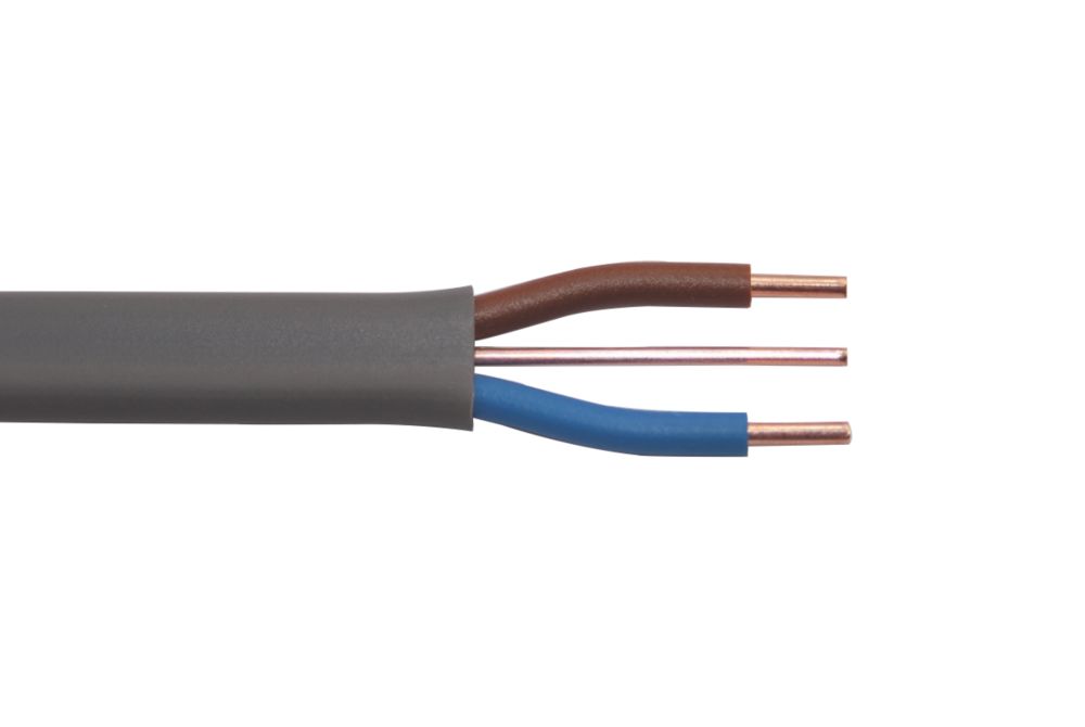
I’ve measured a few different pieces of our 6242Y 2.5 mm2 (this is the flat/oval type of cable used in the UK - picture below), and the width varied from 10.0 mm to 10.3 mm.
(Not that you’d put a c.t. on that - it won’t work!)
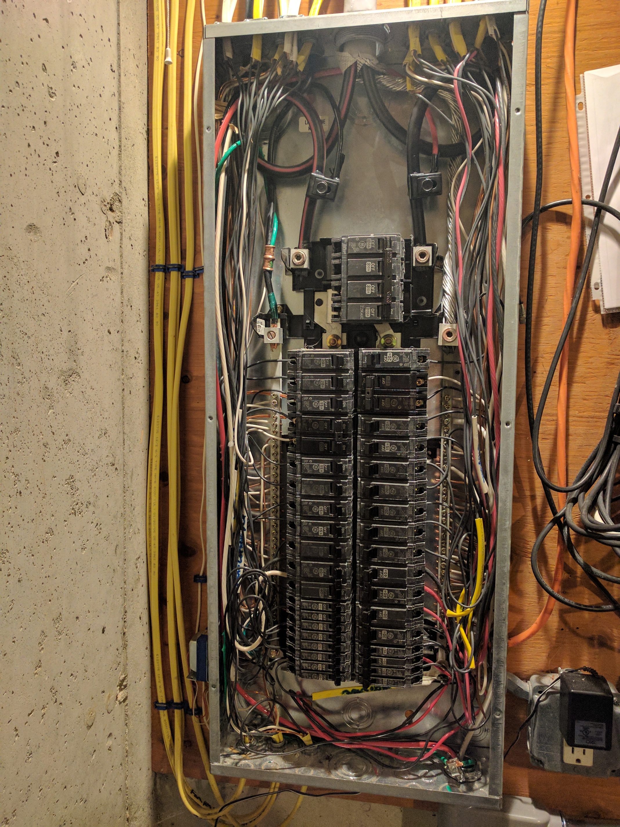
All circuits identified have a neutral line. I think I want to start with the 5 240v circuits and the 120v furnace circuit. That puts me at 6 circuits total. If I want to do an emonPi + 1 emonTx I will have to join the CTs on the 240v circuits. Being familiar now with the space I have inside the panel, I will choose the CTs next. Once I id the CTs, then I can look into joining them, and the details that come with that effort.
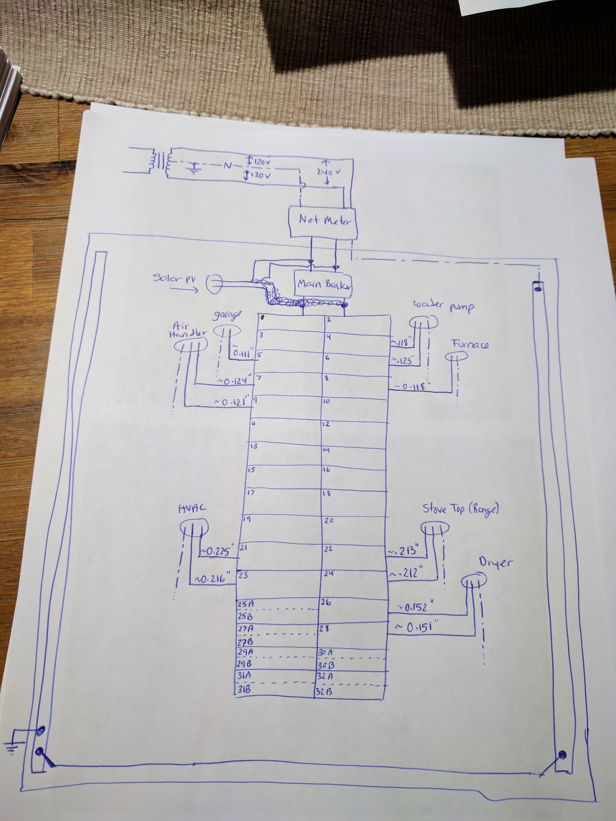
In the attached hand sketch, the enphase CTs will be between the meter and the solar PV lines junctions with the main lines ( I sketched it wrong the first time…excuse the scribbles )
There are two blade switches for the solar system. One outside next to the utility company net meter enclousure, and one inside next to the panel. It’s an OR gate. Either one will shutdown the solar system and isolate it from the grid. I don’t think they are breakers. I can check the print. The print has all those details. I am almost certain there are no actual breakers upstream the main breaker. The main lines are always hot unless the utility opens the net meter enclosure and turn the power down with their blade switch.
I think I will purchase magnelab CTs. I think their models are the closest fit to my circuits. When I chose magnelab CTs, what voltage rating should I select? 1, 2, or 5 volts?
Choose the 1 V output option. The emonTx & emonPi require about 1.1 V rms at maximum input, so you’re not losing much. That 1 V is a guaranteed accuracy (within the limits on the data sheet). (But noting that you still have the (in)accuracy of the reference voltage and the ADC to add, so it’s not 1% overall current accuracy.)
You will need to remove the burden resistor on each of the inputs of the emonTx and the emonPi - it is the larger resistor on the PCB immediately behind the input socket, with a hole for a wire-ended resistor just beyond each end.
If you want total freedom, unburdened is the most versatile. You can then choose the value of burden resistor to trim the sensitivity (upwards - lower maximum current, but within limits) to suit. The downside of that is, the absolute accuracy will be a bit worse because you won’t be able to trim the burden value. But you’ll need to solder in your new burden resistor in parallel with or instead of the internal one - depending on the value you require. I think values are on the N.America page.
Correct. They’re disconnects (Isolators in UK electrical speak, if I understand the term correctly)
(Maybe a candidate for for the UK/US equivalency table on the use in N. America page, Robert?)
That aside, Robert is correct, the PV system should be backfeediing a circuit breaker. That breaker can be in the load center, or it can be in a separate enclosure. So, one of those disconnects of which you speak, may be a fused disconnect.
If you’re not in a hurry, you can save quite a bit of money by choosing Wattcore CTs. The Magnelab units are good stuff, but they tack on a $50 non-refundable engineering fee as the 1 Volt units are considered a special order.
Wattcore has CTs with 1 Volt output as part of their regular retail line. i.e. no extra charge for the 1 Volt output option. The downside to the Wattcore CTs is the time it takes to get them - about 3 to 4 weeks. I have four WC-1 CTs and am happy with them. I have four Magnelab SCT-0750-XXX CTs and am happy with them as well.
Agreed.
There are roughly three types of these things, in UK terminology and in order (least “good” first)
(bolted) Link - Can only isolate part of a circuit when the whole circuit has been isolated and made safe elsewhere
Off-load isolator - can be operated ‘live’, but as it says, it cannot break any significant current.
On-load isolator or switch - this can safely break the normal operating current (e.g. a normal domestic switch)
Circuit breaker - can safely operate and interrupt the circuit under defined fault conditions (meaning that the fault current must be limited to some value, most often by the upstream supply impedance, transformer impedance, cable resistance or a combination of these. A circuit breaker normally includes circuit protection mechanisms, e.g. and overcurrent trip.
I rather think not - at least if it is 240 V. If it is 240 V, you must break both legs in order to assure safety, and you can only do that using a pair of linked circuit breakers.
If you have two fuses and one ruptures, you can believe the apparatus is safely isolated because it is not operating, when in fact one leg remains live.
Quite right. But, in this instance, the device’s purpose isn’t that of an OCPD, but rather that of an isolator. Both legs get disconnected downstream of the device when it’s switched off.
I could not find wattcore CTs as small as what magnelab offers. I think I cant use the OEM blue split CTs in my < 0.25" wires. Correct?
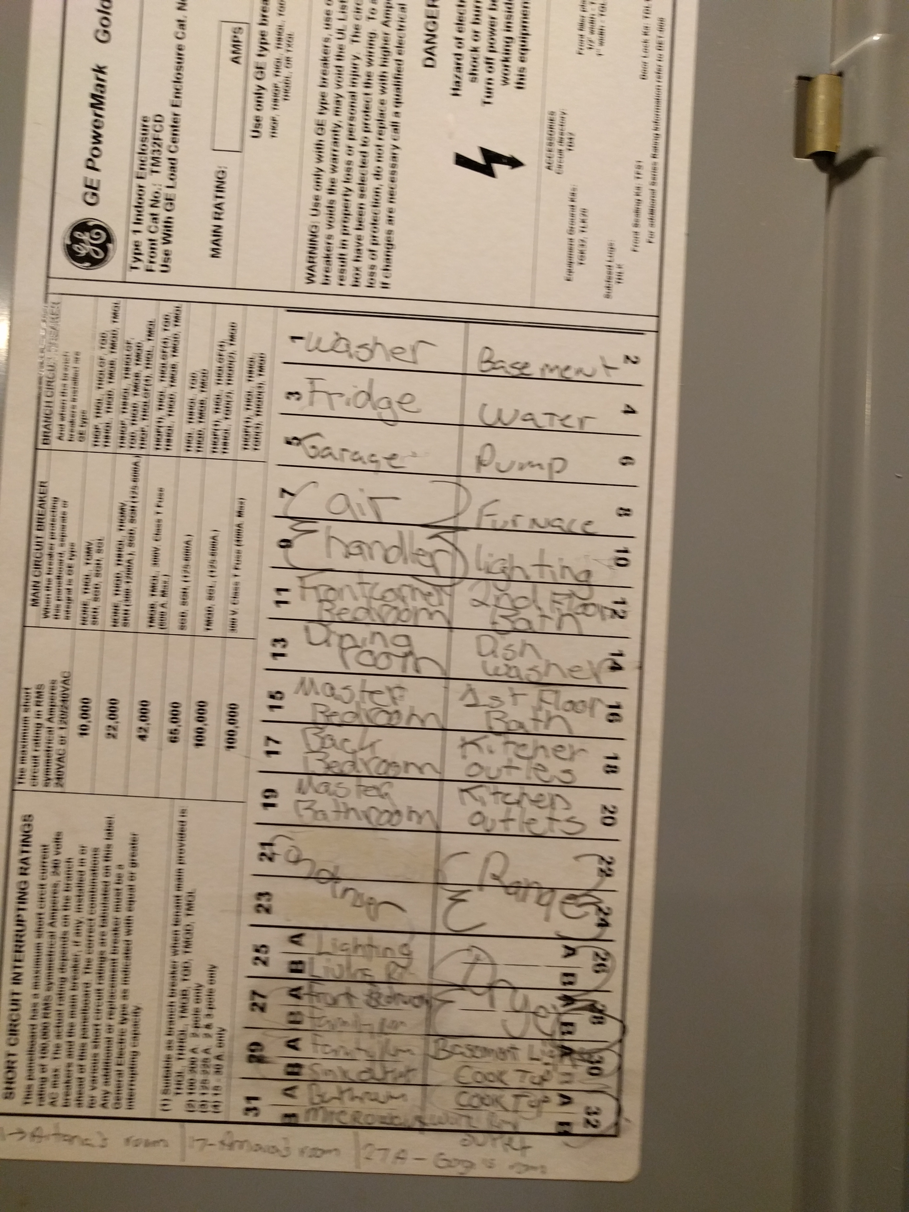
I identified the following:
five (5) 240v circuits:
1.1 Air handler @ 20A breaker each: 2 x UCT-0300-000 (1V option)
1.2 Water pump @ 20A breaker each: 2 x UCT-0300-000 (1V option)
1.3 Dryer @ 30A breaker each: 2 x UCT-0300-000 (1V option)
1.4 Stove Top @ 40A breaker each: 2 x UCT-0500-000 (1V option)
1.5 HVAC @ 40A breaker each: 2 x UCT-0500-000 (1V option)
1 floating 120v circuit (to be changed around as desired) with breaker of < 30 A: 1 x UTC-0300-000 (1V option)
That is a total of 6 circuits (emonPi + emonTx) @ 7 UCT-0300-000 and 4 UCT-0500-000, both 1V option. I am still short 4 CTs I wanted to monitor the same circuits enphase is monitoring…and that means I am short an emonTx as well. That would be a future expansion.
If I choose a “No Burden resistor” option for the magnelab CTs, I assume the amp rating will be according to what resistor I select but not to exceed 30A for the UCT-0300-000, and not to exceed 60A for UCT-0500-000. Correct?
Robert / Bill, If I understand correctly, the emonPi and emonTx come with resistors calibrated to work with the blue OEM CT. Changing resistors is required if I select a different CT (like in my case, magnelabs). Your statement below:
My interpretation is that I can replace the internal resistor (designed for the blue OEM CT) for the resistor I require, or add another one in parallel to the internal one so my resulting resistance is what I need. Correct?
I am learning quite a bit, and almost ready to down select CTs.
Is 0.25" the overall diameter? If yes, you can, because the aperture of the SCT-013-xxx is 13.0 mm (0.51").
In theory, yes. But Magnelab assure us that their c.t’s can operate with a substantial overload, so if you want to go a little way over the 30/60 A, it should be OK with a suitable burden. But you do lose a bit of accuracy as you increase the burden resistor value to increase the sensitivity. So it’s still best practice to get the correct c.t., which is the one that can just cope with the maximum current the load can draw.
Correct both times. (Specifically, both are designed for the SCT-103-000. The others in the SCT-013 range require the burden resistor removed.
That is indeed correct. You choose the standard resistor lower than the value that will give 1.1 V at the maximum current you want to measure (rms values). So if you want 60 A using a 100 A : 50 mA c.t, the resistor is 1.1 V / 30 mA. (You’d choose 36 Ω ± 1%, or failing that, 27 Ω.)
Were you speaking of solid core or split-core CTs? Physical dimensions, or elctrical rating?
Wattcore has a 25 Amp split-core CT with 1 Volt output, as well as a 50-Amp unit.
What you want to avoid is a tight fit. The CT jaws need to mate fully. Any gap between them, even a small one, causes the CT to yield incorrect measurements. A loose fit makes it easy to ensure the CT jaws close sans a gap.
 )
)