You’re talking about the current value or the power value ?
either!
The question I’m asking is are the results/readings different depending on what the Arduino USB is connected to whilst the measured circuit remains unchanged.
I’ve checked and the results are very close to each other no matter if it’s between Arduino and PI or Arduino-USB
Edit 1 : When i have not connected my system to my DC PS , my power value must be 0 right (even with noise) ? Cause even when i adjust my étalonnage value , i haven’t a correct value for I1
EDIT2 : Without connecting the DC PS , i’ve got some good values ( close to 0) . But when i just connect de DC PS with my system my values reach like for example power1 = -15.
So my DCPS could be the probleme here ?
Correct
Maybe not with noise present. If necessary, you can filter the noise out with a filter in the software. But first, let us try to get sensible readings.
Why not? How is it incorrect?
Have you declared étalonnage as a double?
When you write double étalonnage = 1.0, and 10 A flows IP+ to IP-, what value of current do you read?
The value of that means nothing until you can read the correct value for current. If you have a negative value, it means that you have a current flowing the wrong way in the ACS712. You should read a positive value when current flows from IP+ to IP-, and negative when current flows from IP- to IP+
Which is “DCPS” ? Is it the power supply that you are using to give the test current flowing in the ACS712? You must have only that connected to IP+ and IP- , there must be no other connections. If there are, that might be what is causing the confusion.
@Atelier21
Looking at your circuit diagram, there is something that will cause a problem in the future, if it is not causing you a problem now. This is the connection to the Arduino pin A4.
First, are all the black lines marked “GND” connected together? I do not believe they are, and if I am correct, you will not read the correct voltage on pin A4, because it measures with reference to the Arduino GND.
Second, and much worse, you might already have damaged your Arduino, because you must not put a voltage greater than 5.0 V on any analogue pin - including pin A4. When you have the connections as shown in your diagram, the voltage at pin A4 is at 24 V (from “vers la batterie”) × 1.2 ÷ 2.2 plus the difference in voltage between vers la batterie GND and Arduino GND. 24 × 1.2 ÷ 2.2 = 13.09 V. That is not good.
I’m using a second system which deliver 5V in output and this output is connected with an input of my system (i don’t if i’m clear, i can take a photo of the system to be more clear if you want and if it’s not excessive) : I don’t connect directly my DC power supply in my inputs.
That is not what you have drawn. You have a connection to Arduino pin A4 from the cycle battery circuit.
In my system , it’s the PIN A5 , i may have a mistake in my circuit : i’m not using pin A4 but use A5 for this.
It does not matter which pin - if the voltage between A & B is zero, you have 13.09 V on pin A4, or A5. If point A is at +12 V relative to point B, you have 13.09 + 12 = 25.09 V on the pin.
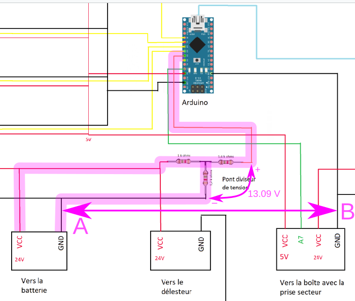
And looking further, what is the MBR4045PT doing? As you have drawn it, all 3 connections go to the same place, so it has no function in the circuit.
Maybe a mistake in the drawing but i assume that i’m using it to help the batteries charging. I’ve taken a photo , it’s far to be clear but i drew on it to be more clear .
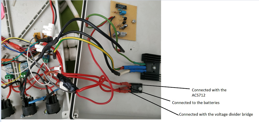
Sorry , i’m doing all i can to be clear , i’m very sorry for this wires mess.
I can take a picture of all the system but it will be worse than this picture, i’m trying to do my best.
Thanks for answering
You are doing very well, and you understand English much better than I understand French. Do not worry about that, I am trying to help you as best I can.
I am certain that there is a mistake there. I can only help you using the information that you tell us, if that is not correct, what I suggest to you might be wrong.
The lower-left setup is used to compare the battery charge with the power sent by the generators, and the potentiometer sets a value from which the current is sent back to the halogen(i want to use halogens like dischargers on my circuit) rather than to the battery.
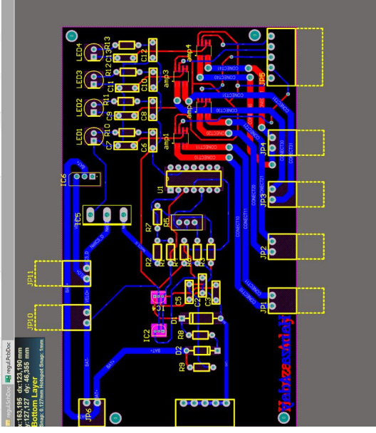
I think that i have some problems relatives to my circuit that may cause all the issues.I may take the time to redraw a better and more clear schema.
Thanks for taking your time to answer,
No, sorry, without the proper circuit diagram, that does not help me.
I figured out my issue , i’ve got some coherent value by reading directly on my arduino monitor (i can vary my input with my DC generator and the current red is approximately good) but i don’t know why it works on my arduino monitor ( in my computer) but the values don’t vary on my emoncms local server , any ideas ?
EDIT1 : I always need to restart emonhub config to refresh the values of power , don’t know why
I wrote that one week ago.
There was a reason why I wrote that. It is because when I am trying to solve a problem, the fewer places there are where the problem could be, the better.
So you are now saying that there is not a problem measuring the current and calculating the power in your Arduino, and the problem lies in sending the value to emoncms. Correct?
How are you trying to send the values to emonCMS? How is your Arduino connected to your network? Is your local server where you are running emoncms?
Yes , there are some differences between theorical value and what i see but the gap is very small.
I have connected my Arduino using a sketch which calculate power value and send them directly to my RPI3 (which i use to communicate in real time in my emoncms local server)
For each of the bolded parts in that section… How, how and exactly how?
1 Like
I’m using an USB cable between my Arduino and my RPI3.
I’m using this sketch :
#include <EmonLib.h>
#include <stdio.h>
#include "EmonLib.h"
// Include Emon Library
EnergyMonitor emon1;
// Create an instance

EnergyMonitor emon2;
// Create an instance

EnergyMonitor emon3;
// Create an instance

EnergyMonitor emon4;
// Create an instance

//https://github.com/openenergymonitor/learn/blob/master/view/electricity-monitoring/ct-sensors/how-to-build-an-arduino-energy-monitor-measuring-current-only.md
void setup()
{
  Serial.begin(9600);


  emon1.current(A0, 111.1);               // Current: input pin, calibration.
  emon2.current(A1, 111.1);             // Current: input pin, calibration.
  emon3.current(A2, 111.1);             // Current: input pin, calibration.
  emon4.current(A3, 111.1);             // Current: input pin, calibration.

}
  const int decale1 = 509 ;
  const int decale2 = 501 ;
  const int decale3 = 502 ;
  const int decale4 = 503 ;


/*void loop() {
  int valeur = analogRead(A0);
  Serial.println(valeur-decale1);
  delay(250);
}
 */
void loop()
{
  const double etalonnage1 = 0.027;
  const double etalonnage2 = 0.027;
  const double etalonnage3 = 0.027;
  const double etalonnage4 = 0.027;

  const double tension = 24.0;

  int power1;
  int power2;
  int power3;
  int power4;

/*void loop() {
  int valeur = analogRead(A1);
  double valeur3 = ((valeur-decale2)*etalonnage2);
  double valeur4 = valeur3 - 0.3;
  double valeur2 = (((valeur-decale1)*etalonnage1)-0.3)*24.0;
  Serial.println(valeur4);
  delay(250);
  // Calculate Irms only

} */


//  Add a leading node id eg
  Serial.print("6");
  Serial.print(" ");


 // calculer et afficher le courant 1
double I1 = (analogRead(A0)-decale1) * etalonnage1 ;// Calculate Irms only
power1 = I1*24.0 ;
Serial.print(power1);         // Apparent power
  Serial.print(" ");
  //Serial.println(Irms1);          // Irms
  //FIN

   // calculer et afficher le courant 2
double I2 = (analogRead(A1)-decale1) * etalonnage2;  // Calculate Irms only
power2 = I2*24.0 ;
Serial.print(power2);         // Apparent power
  Serial.print(" ");
  //Serial.println(Irms2);          // Irms
  //FIN

   // calculer et afficher le courant 3
double I3 = (analogRead(A2)-decale3) * etalonnage3;  // Calculate Irms only
power3 = I3*24.0 ;
Serial.print(power3);         // Apparent power
  Serial.print(" ");
  //Serial.println(Irms3);          // Irms
  //FIN

   // calculer et afficher le courant 4
double I4 = (analogRead(A3)-decale4) * etalonnage4;  // Calculate Irms only
power4 = I4*24.0 ;
//printf("%lf",power4);
Serial.print(power4);         // Apparent power
  Serial.print(" ");
  //Serial.println(Irms4);          // Irms
  //FIN

  Serial.println();
}
I’m using the EmonPI SD image on my RPI3 , i’ve configured a static IP on it and using this ip to connect it to the emoncms local server.
From your reply, your sketch is simply printing values to the serial port as space separated, are you using emonHub to translate that and insert it into EmonCMS? If so, how do you have emonHub configured?