So, I have everything connected to the panel and to the emonTx. But, in EmonCMS, all values are showing N/A / NULL for the EmonTX.
That means that data is not reaching emonCMS.
What physical setup did you end up with? I know an emonTx, what’s the base station?
Do you have a programmer?
Does the emonTx appear to be working - i.e., does the internal LED flash roughly every 10 s?
If you look at the emonHub log in emonCMS → Setup → emonHub, does that give any indications?
emonTx connected to emonBase via the radio connection. I do have a network switch near the emonTx which I could use for a wired connection. The emonTx LED is flashing.
Nothing obvious in the log:
2021-09-08 03:44:58,005 INFO MainThread Setting RFM2Pi calibration: 230V (1p)
2021-09-08 03:44:59,007 DEBUG MainThread Setting RFM2Pi pubchannels: ['ToEmonCMS']
2021-09-08 03:44:59,008 DEBUG MainThread Setting RFM2Pi subchannels: ['ToRFM12']
2021-09-08 03:44:59,010 INFO MainThread Creating EmonHubMqttInterfacer 'MQTT'
2021-09-08 03:44:59,013 DEBUG RFM2Pi acknowledged command: > 1p
2021-09-08 03:44:59,016 DEBUG MainThread Setting MQTT pubchannels: ['ToRFM12']
2021-09-08 03:44:59,017 DEBUG MainThread Setting MQTT subchannels: ['ToEmonCMS']
2021-09-08 03:44:59,018 INFO MainThread Setting MQTT node_format_enable: 1
2021-09-08 03:44:59,018 INFO MainThread Setting MQTT nodevar_format_enable: 1
2021-09-08 03:44:59,019 INFO MainThread Setting MQTT nodevar_format_basetopic: emon/
2021-09-08 03:44:59,020 INFO MainThread Setting MQTT node_JSON_enable: 0
2021-09-08 03:44:59,021 INFO MainThread Creating EmonHubEmoncmsHTTPInterfacer 'emoncmsorg'
2021-09-08 03:44:59,023 DEBUG MainThread Setting emoncmsorg pubchannels: ['ToRFM12']
2021-09-08 03:44:59,024 DEBUG MainThread Setting emoncmsorg subchannels: ['ToEmonCMS']
2021-09-08 03:44:59,024 WARNING MainThread Setting emoncmsorg apikey: obscured
2021-09-08 03:44:59,025 INFO MainThread Setting emoncmsorg url: [https://emoncms.org](https://emoncms.org)
2021-09-08 03:44:59,026 INFO MainThread Setting emoncmsorg senddata: 1
2021-09-08 03:44:59,026 INFO MainThread Setting emoncmsorg sendstatus: 1
2021-09-08 03:44:59,323 DEBUG RFM2Pi acknowledged command: i - set node ID (standard node ids are 1..30)
2021-09-08 03:44:59,429 DEBUG RFM2Pi acknowledged command: b - set MHz band (4 = 433, 8 = 868, 9 = 915)
2021-09-08 03:44:59,537 DEBUG RFM2Pi acknowledged command: o - change frequency offset within the band (default 1600)
2021-09-08 03:44:59,743 DEBUG RFM2Pi acknowledged command: g - set network group (RFM12 only allows 212, 0 = any)
2021-09-08 03:44:59,846 DEBUG RFM2Pi acknowledged command: c - set collect mode (advanced, normally 0)
2021-09-08 03:45:00,054 DEBUG RFM2Pi acknowledged command: ..., a - send data packet to node , request ack
2021-09-08 03:45:00,160 DEBUG RFM2Pi acknowledged command: ..., s - send data packet to node , no ack
2021-09-08 03:45:00,267 DEBUG RFM2Pi acknowledged command: q - set quiet mode (1 = don't report bad packets)
2021-09-08 03:45:00,374 DEBUG RFM2Pi acknowledged command: x - set reporting format (0: decimal, 1: hex, 2: hex+ascii)
2021-09-08 03:45:00,690 DEBUG RFM2Pi acknowledged command: ,,, f - FS20 command (868 MHz)
2021-09-08 03:45:00,797 DEBUG RFM2Pi acknowledged command: ,, k - KAKU command (433 MHz)
2021-09-08 03:45:01,003 DEBUG RFM2Pi device settings updated: E i5 g210 @ 433 MHz q1
(I’ve put some carriage returns in to make it readable ![]() )
)
It looks as if it should be receiving, but there’s no evidence of anything being received. How far away is the emonTx? And what is in between them?
Do you mean make a (short) wired connection between your emonTx and the base, and then Ethernet / WiFi into your LAN?
The emonTx is located in the electrical closet and the emonBase in the utility room. Between them are a few walls, so there may be sufficient interference to reduce the signal strength.
I moved the emonTx so it’s not obscured by a receiver unit. Still no data after a reboot.
In the absence of a means to establish whether the emonTx is not transmitting, or the emonBase is not receiving, it’s quite hard to progress this.
Yeah, I’m a full stack software developer. 
I mounted the emonPi in the closet where the emonTx is. Now I’m getting data.
So it’s a matter of too much attenuation in the radio path, normally (in the UK) that’s due to thick stone walls in older houses, but it can also be due to foil-backed insulation, which is very good at blocking radio signals.
The brother-in-law of a friend lives in a town house near the centre of Edinburgh, the walls are solid sandstone, and he can’t get WiFi outside the room where the router is.
It sounds as if your emonBase needs to remain close and use the Ethernet, rather than WiFi, to get into your LAN.
I see one of my power monitors is showing a negative value and one is showing positive. I’m guessing one of the sensors is upside down?
Take a look at the diagrams in the “Use in North America” page, paying attention to the phase dots.
Got it.
It’s unclear what the DIP switch position should be for US.
https://wiki.openenergymonitor.org/index.php/EmonTx_V3.4#DIP_Switch_Config
And one of the power values is still showing as negative.
It does actually say: “Default DIP switch selection (both off) is node ID 10 and 240V AC.” and the switch itself is labelled. So the switch should be ON for you.
I take it you have a US-type split phase 120 - 0 - 120 V supply. Have you installed the c.t’s as shown on the page I linked? In other words - if you follow the current for a 240 V load around - flowing in (say) on the ‘A’ leg, through the load and out on the ‘B’ leg, both c.t’s should see the current flowing through them in the same direction - always assuming you’ve connected their wires to the jack plugs consistently.
Ahhhh. I understand now. I thought both DIP switches were involved. OK. So D8 is now set to On which is USA. Cool, so that’s all good. And now I see what you mean about the current. So, I just need to flip one of the CTs around in the box and it should be good.
I really appreciate all your help. Having mentored many junior developers, I know what it’s like to help someone so new to the process.
1 Like
Flipped the CT which was showing negative and now P1 and P2 are both positive.
I realized my AC plug for the emonBase was plugged in backwards, so I swapped that around.
I still see that I’m getting both positive and negative numbers coming back from the CTs.
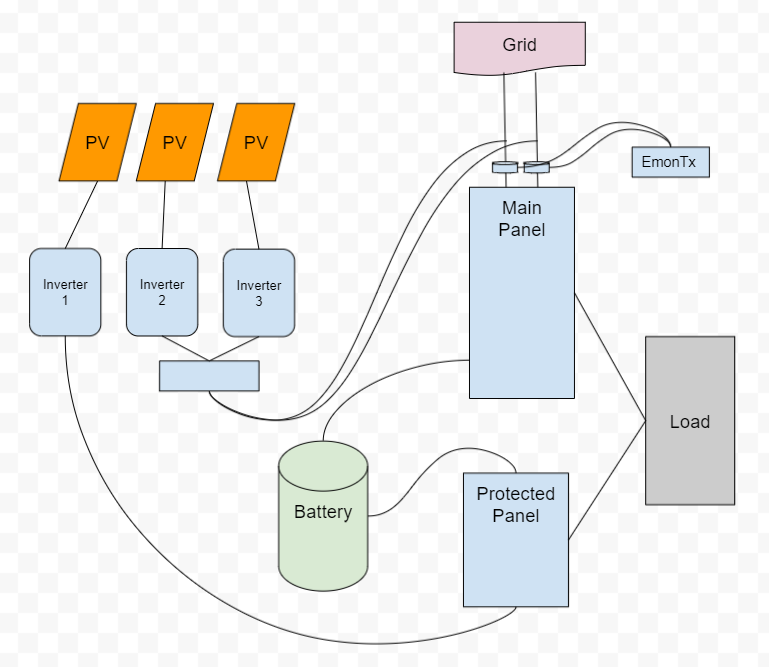
Here’s what my hosue looks like:
Edit: deleted link to diagram that is already attached to post. Moderator - BT
That will reverse both c.t. outputs, so the one that was positive will now be negative, and vice versa. There’s more about phase relationship and the direction of power flow in Learn→Electricity Monitoring→AC Power Theory→Introduction→An Introduction to AC Power
But - is it genuine export? If Inverter 1 can feed via “Load” back into “Main Panel” then that could well be happening if the inverter generates more than Load requires.
I’ve seen both CTs in positive, and both in negative, and a mix.
At the CT, it would have to be genuine export because the only other place it can go is to is out to the other two inverters. I wouldn’t think that’s possible.
So, if I want to measure total household usage, I would need to put the CTs upstream from the solar connection to the main panel. Then I would need to look at total solar production which I could pull down from the SolarEdge API. Then I could net everything out.
I was hoping to avoid all that by putting the CTs where they are in the diagram, but that doesn’t seem to be sufficient.
What’s confusing me with your diagram is Load appears to be fed both from Main Panel and from Inverter 1. And is Battery actually an inverter/charger doing UPS duty for the Protected Panel?
The way it is wired now, according to your diagram and if I’m reading it correctly, means that the Load is supported by the grid plus all three inverters. Inverters nos. 2 & 3 will feed either load or export depending on the availability of PV generation and the house load. The c.t’s see the nett power coming from the Grid or being exported from Inverter 1.
I don’t see why it shouldn’t be. If you stay as you are, house use is PV1 + the emonTx total, and the emonTx total can (is expected to) go negative if PV1 is generating more than the house is using.
If you move the c.t’s to the grid side of the feed-in from the PV, the emonTx would measure the nett grid power, and the inverters would give you total generation. Your house use (overall, not instantaneous because some might be being stored or released by the battery) is then Grid + 3 PV’s, bearing in mind Grid will go negative when exporting, when the load is less than the 3 PV’s together are generating.
So, the battery acts as a passthrough for power from the main panel. But, it also supplies power as needed to reduce external draw. And, it can be set to fully charge itself to act as a UPS in the event of a power outage.
So, I think I need to determine full energy usage as you suggested.
Is there a section of the guide which goes into more detail about how to merge various data points together for visualization?