Regarding the valve, yes this appears to be a bypass although reasons why you’d want to do this I’m not sure.
It’s shut but just to prove I cracked it open tested the flow rate which showed an increase then shut it off again.
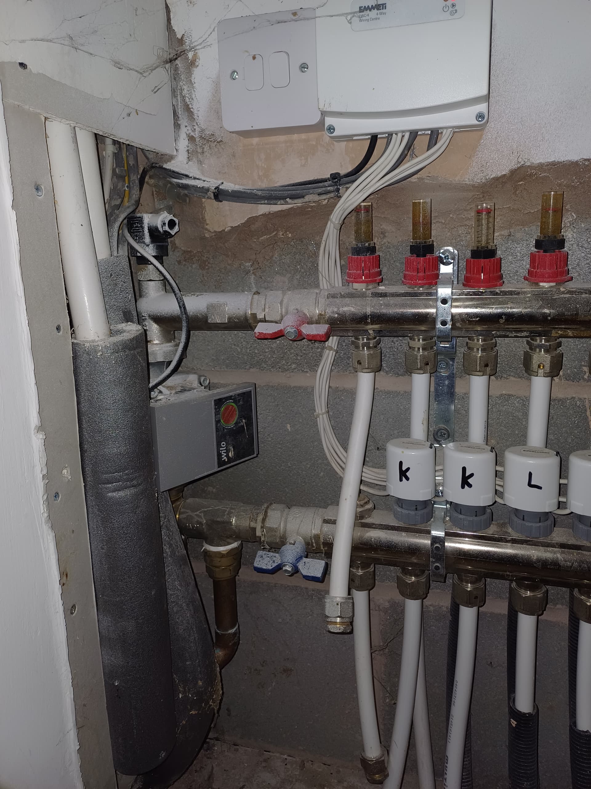
I still think 14l/min is low for the top speed on the Mitsubishi-supplied system pump. (The settings in the controller won’t have any effect on the speed as the pump doesn’t look like it is a PWM-controlled variety.) You are then splitting that flow rate between two zones - surely this will mean the flow rate is even lower in each zone and so the flow temp has to be higher to get the right amount of heat in.
Tim has highlighted the empty looking clip where the thermistor should be - is it in, out, partially out? If the system is not getting accurate measurement of the flow temps then this will skew its performance and the calculation of heat delivered.
Only a small update but I’ve tested both the thermistors today in some warm water to make sure they’re both reading the same and appears they are. For some reason the flow thermistor body is larger than the return which I cannot understand.
I’ve reattached in original locations using some aluminium tape rather than the bonded copper tabs and also covered with some pipe insulation.
Next jobs are to flush the system and insulate all the pipes which should hopefully increase heat transfer and give more accurate readings from the thermistors and see more delta T.
Hi all.
Just to update this thread following some further work/investigation.
Following from last post I’ve now flushed out the system which was a good job done and was well over due judging by the colour of it. I haven’t seen the flow rate increase but I still need to open up the filter housing and hopefully this will see some increase.
On a whole the system appears to be now running much efficiently showing a COP of 2.38 on the controller with Feb showing; 50kW consumed, 119 delivered. It’s good to see efforts paying off.
In summary all I’ve done is flush the system, switch to auto adaption, and lag the pipework on the pre-plumbed unit.
Now what I’ve discovered is that it appears the two zones are fighting one another and potentially causing back flow on the LLH to the UFH.
With the flow rate set to 40’C on controller and just the UFH active (Zone 2) the manifolds saw 38’C flow and 31’C return. When Zone 1 (the upstairs rads) is activated the temp drops immediately in seconds to 27’C flow/25’C return for the UFH and I see 38’C at the rads instead. What’s interesting is this 27’C flow is lower than the return flow temp of 35’C to the ASHP so how is this possible? Cycling between the HOT/COLD manifolds?
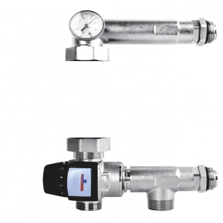
After looking at the UFH setup I see a brass tee-piece instead of where you normally see a mixing valve.
I have contacted Emmeti support for info on the system and to check over the piping however they weren’t very helpful only suggested it doesn’t look right and it’s an old system and that’s all they could say.
Having searched online to try find this connection I’ve only seen it with a mixing valve fitted so I decided to investigate to see what’s going on between the HOT/COLD returns.
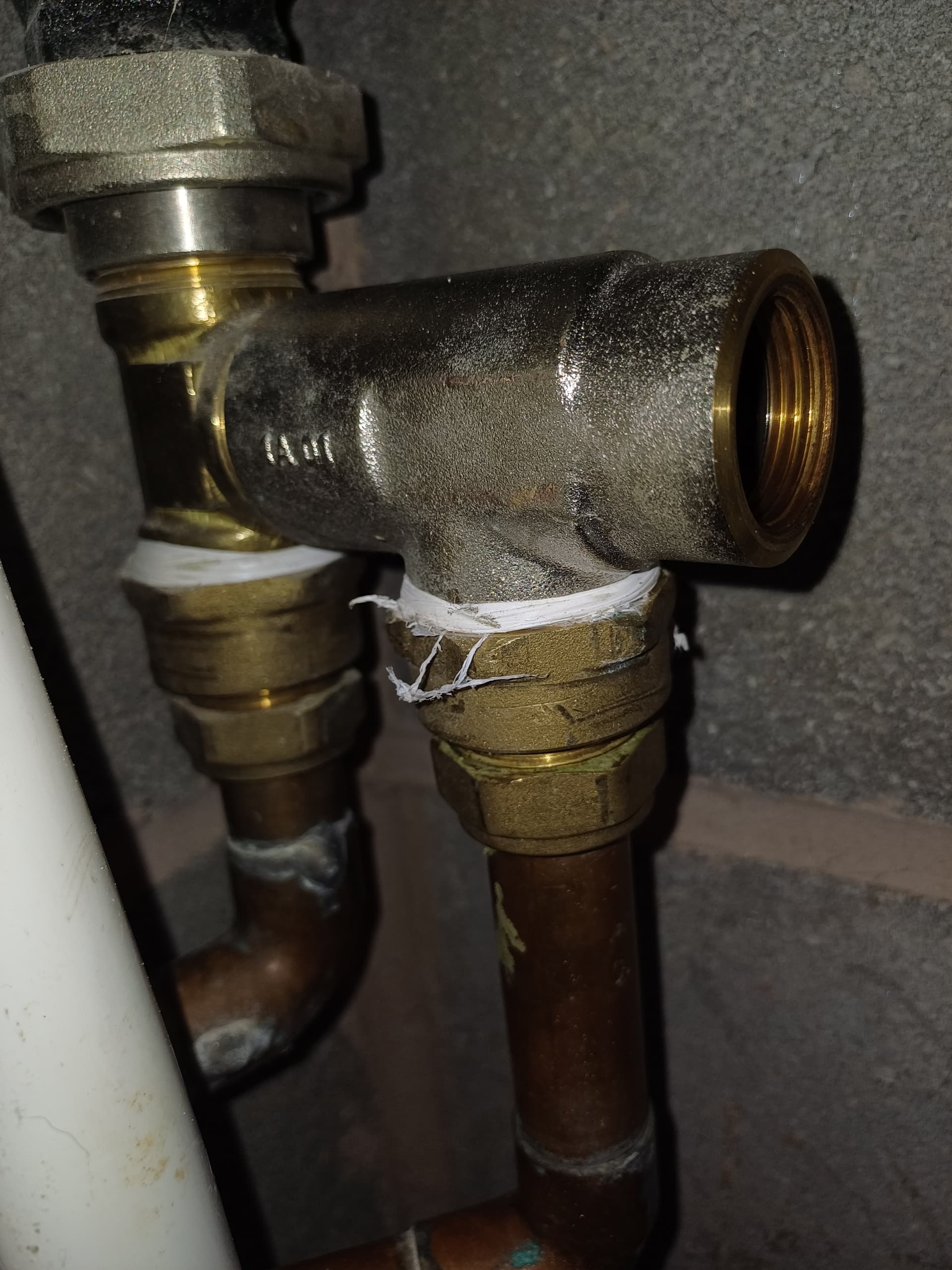
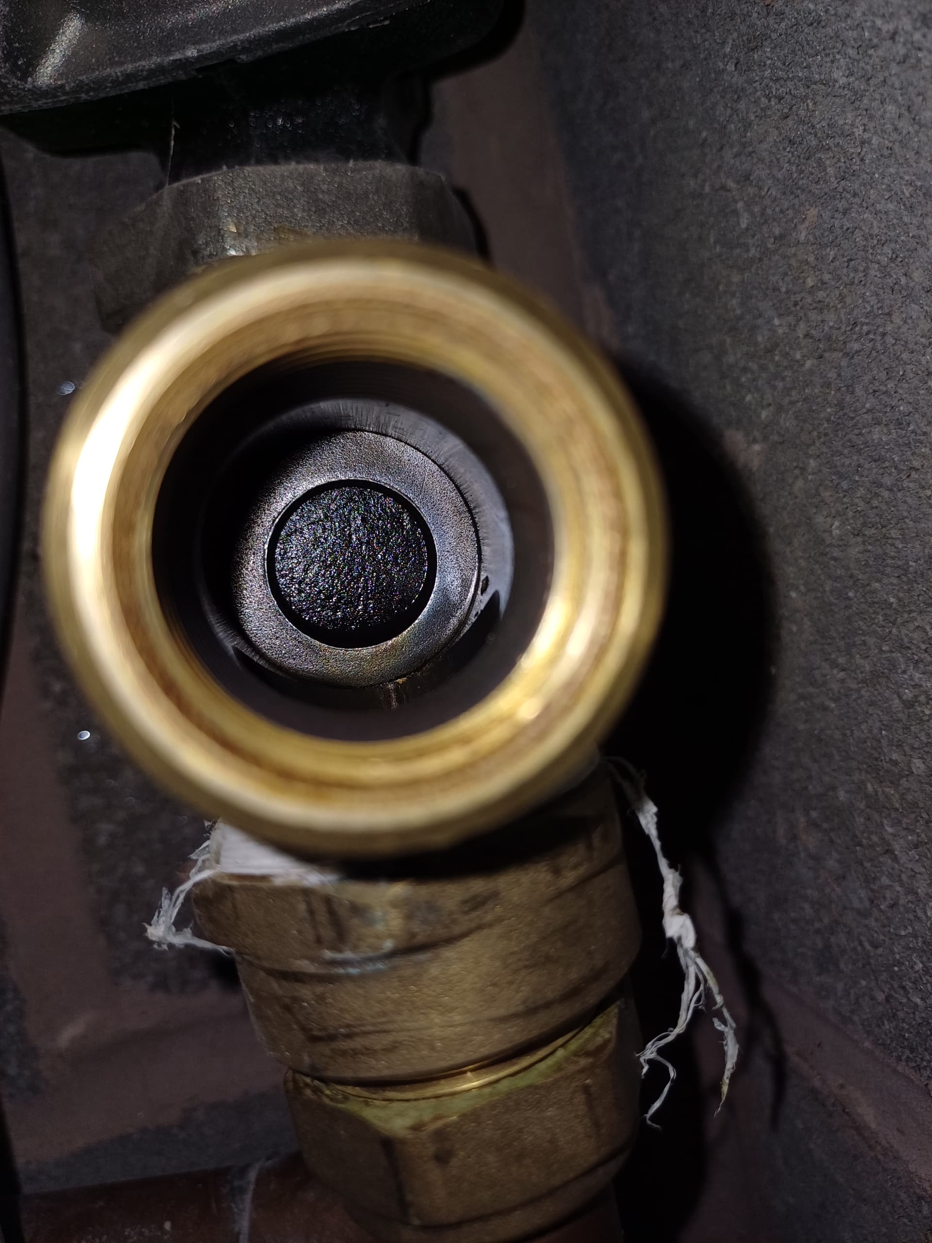
Unfortunately I couldn’t get any further than this as the t-piece was solid and I didn’t want to take the heating out of action with this cold spell upon us.
Can anybody confirm what this connection is and it’s purpose.
Is there any reason the manifolds can’t just take a flow and return to the LLH?
Cheers,
Vince.
looks like you have the 3rd loop in turned off even though the actuator is open. couldn’t see the rest but you need to check them. also start with 2lt/min flow rate for all zones.
The adjustable flow temp/mixer has been disabled so you can leave it. you are getting direct temp from air source to the underfloor loops.
if your underfloor rates are all above 2 that could have an effect when you have both zones on. but also check that the rads are balanced. lockshield open 1.5 turns on each rad