Low COP - Ecodan Cycling

What was the calculated heat loss for your property? How big is the property (in m²)?

On January 18th, what was the average outside temperature, and how much electricity (kWh) did the heat pump consume that day? Was the house warm enough?

Sorry, one more: what is your weather compensation curve set to?

To pre-empt answers to my question, and mostly so I don’t forget it, I checked the performance measurements from HeatpumpMonitor.org for some other, similar-sized systems on that day:

  • System #73 consumed 23 kWh and generated 78 kWh of heat, COP of 3.4. Average -1.5 °C.
  • System #67 consumed 33 kWh and generated 94 kWh of heat, COP of 2.8. Average -0.3 °C.
  • System #56 consumed 43 kWh and generated 103 kWh of heat, COP of 2.4. Average 1.0 °C.

This shows the sort of consumptions you might expect to see on “design day”.

:man_facepalming:

And folk wonder why ASHPs get such a bad rep. Is this a scheme of houses?

One thing you could try is see if there is a Heat Geek installer near you and get them to have a look.

1 Like

Sad face.

Hopefully not long till I get this huge radiator in the hall installed and things start to improve.

1 Like

The other thing I notice about your flow temperature is that it is very low at 25°C. This will most certainly result in cycling. I would recommend adjusting the curve so the minimum is, say, 30°C, and see how that changes the behaviour. Hopefully the room thermostat will step in if the house gets too warm?

You’re right Tim and looking at last nights colder spell below 10’c i can see how the cycling stabilised. I have to admit here this is my doings/experiment with the weather curve trying to find lowest flow temp setting to achieve 18’c seen in a bedroom for the higher ambient temp setting (i hope this makes sense because it even confuses me reading it back).

Does this conclude its impossible to opt the method of running with thermostats set to max/calling for heat as recommended for highest COP because anything over 10’c outside and the system will just cycle as we’re seeing.

I’m thinking the next test it to try the auto adaption and see how that performs being the ‘smart’ method.

I feel it may be worth need more temp data from the system too for the up and downstairs legs?

While this is the “optimal” way to run a heat pump, it doesn’t work if the heat pump is oversized for the property. The minimum heat output of your unit is maybe 3 kW, and if your emitters cannot output* that heat at 25° then there’s no where for that heat to go. Flow temperature goes up until it exceeds the weather compensation limit, and the heat pump shuts down for a few minutes before restarting. Those short cycles will typically have poor performance, and wear out the compressor.

*At 5° above room temperature, your radiators will only be able to output 5% of their rated output.

Anecdotally, this has worked quite well for some owners, myself included. In this mode, the flow temperature is left to go up to where it stabilises, and will produce long runs with good performance. When the room temperature reaches 1° above set point, the heat pump turns off (eventually). It’s worth experimenting with, even if only to better understand how your heating system responds.

Here’s a snapshot from my system, running with room auto-adapt. The flow temperature tends to reach 40°C regardless of the outdoor temperature, cos the heat pump is about twice the size it needs to be.

Though 14 l/min is within the flow range for the 8.5kW unit I would expect the max pump speed of 5 to be producing something closer to the 24.4 l/min top of the range.

If you have the Ecodan pre-plumbed cyclinder, which I am inferring you have from the LLH reference, then the literature mentions a required primary flow rate of 25.8 l/min. I’m not exactly sure of the reasons for that, but if I am reading the pump chart right for the secondary pump installed on the pipework then even on the lowest speed setting it is just balancing the flow rate at the highest setting for the primary pump. So there might be quite a difference between when you have two running.

This is good feedback Tim and hopefully I also see positive results once switch to the auto adaption.
I just need to relocate the controller as its currently in the cupboard with the tank and seeing 25’C room temp. I’ll require this for the temperature feedback as don’t have a wireless thermostat.

Hi Nigel. Thank you for checking the specs and interesting regarding the pump speed. The controller doesn’t seem actually change the speed of the pump if changed between 1-5, only by pressing the buttons on the pump itself. Perhaps this could suggest its wired into the controller incorrectly?


This is the tank setup along with the pre-plumbed LLH?

This very much depends on the pipework - mine can barely manage 16/17 l/min at the top end, due to how far away the outside unit is. I have the pump speed turned down, so am running down 13/14 l/min, which is on the very edge of the manufacturer’s spec, but it works okay.

Yes, that is the low-loss header that comes with pre-plumbed cylinders. You’ll have a main pump that circulates water to the outside unit and back, and secondary pump that circulates water around the radiators/UFH.

Here :point_down: is where I’d expect the temperature sensor for flow to be, just before it enters the 3-port valve. There’s a pre-soldered slot for it.

image

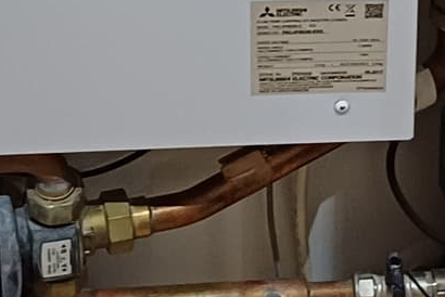
The return sensor is in a similar slot behind the 3-port valve.

You have three options:

  • A. buy their wireless room controller (PAR-WR50R-E) and position it anywhere
  • B. buy their remote room temp thermistor (PAC-SE41TS-E) that can be just outside the cupboard
  • C. move the controller outside of the cupboard

1 Like

What’s going on here, at the bottom?

image

Is this a bypass from flow to return? I hope that it’s firmly off…

2 Likes

So I’ve just managed to relocate the main controller and have now set it to auto adapt.
I might need to change some settings but this now seems to control the circ.pumps for outside unit and the upstairs zone. I believe I might need to get another wireless thermostat for downstairs as when the UFH stats call for heat the circ pump activates on the UFH manifold however the heat pump isn’t kicking in as the main control upstairs isn’t activated.
I’ll let it do its thing overnight and see how it performs.
I’ll flush this system over the weekend too and hopefully might see some increase in flow/thermal transfer.

2 Likes

Regarding the valve, yes this appears to be a bypass although reasons why you’d want to do this I’m not sure.
It’s shut but just to prove I cracked it open tested the flow rate which showed an increase then shut it off again.

I still think 14l/min is low for the top speed on the Mitsubishi-supplied system pump. (The settings in the controller won’t have any effect on the speed as the pump doesn’t look like it is a PWM-controlled variety.) You are then splitting that flow rate between two zones - surely this will mean the flow rate is even lower in each zone and so the flow temp has to be higher to get the right amount of heat in.

Tim has highlighted the empty looking clip where the thermistor should be - is it in, out, partially out? If the system is not getting accurate measurement of the flow temps then this will skew its performance and the calculation of heat delivered.

Only a small update but I’ve tested both the thermistors today in some warm water to make sure they’re both reading the same and appears they are. For some reason the flow thermistor body is larger than the return which I cannot understand.
I’ve reattached in original locations using some aluminium tape rather than the bonded copper tabs and also covered with some pipe insulation.
Next jobs are to flush the system and insulate all the pipes which should hopefully increase heat transfer and give more accurate readings from the thermistors and see more delta T.

2 Likes

Hi all.
Just to update this thread following some further work/investigation.
Following from last post I’ve now flushed out the system which was a good job done and was well over due judging by the colour of it. I haven’t seen the flow rate increase but I still need to open up the filter housing and hopefully this will see some increase.
On a whole the system appears to be now running much efficiently showing a COP of 2.38 on the controller with Feb showing; 50kW consumed, 119 delivered. It’s good to see efforts paying off.
In summary all I’ve done is flush the system, switch to auto adaption, and lag the pipework on the pre-plumbed unit.

Now what I’ve discovered is that it appears the two zones are fighting one another and potentially causing back flow on the LLH to the UFH.
With the flow rate set to 40’C on controller and just the UFH active (Zone 2) the manifolds saw 38’C flow and 31’C return. When Zone 1 (the upstairs rads) is activated the temp drops immediately in seconds to 27’C flow/25’C return for the UFH and I see 38’C at the rads instead. What’s interesting is this 27’C flow is lower than the return flow temp of 35’C to the ASHP so how is this possible? Cycling between the HOT/COLD manifolds?

After looking at the UFH setup I see a brass tee-piece instead of where you normally see a mixing valve.
mixer-set-blending-valve-130mm-pump-wilo

I have contacted Emmeti support for info on the system and to check over the piping however they weren’t very helpful only suggested it doesn’t look right and it’s an old system and that’s all they could say.
Having searched online to try find this connection I’ve only seen it with a mixing valve fitted so I decided to investigate to see what’s going on between the HOT/COLD returns.

Unfortunately I couldn’t get any further than this as the t-piece was solid and I didn’t want to take the heating out of action with this cold spell upon us.
Can anybody confirm what this connection is and it’s purpose.
Is there any reason the manifolds can’t just take a flow and return to the LLH?
Cheers,
Vince.

1 Like