Linknode R4 Wifi 4 Ch Relay Board

@Paul, ah, that is an interesting one. I was actually looking at it from the other direction in informing Node-Red that the relay was not responding. In the exisitng code, you would only know that if you changed a relay and did not get a status message back.

However, yes I think you are right that there should be something that sets all to LOW if node-red fails. The physical wiring of the relays (NO or NC) should determine that, that is a ‘safe’ state.

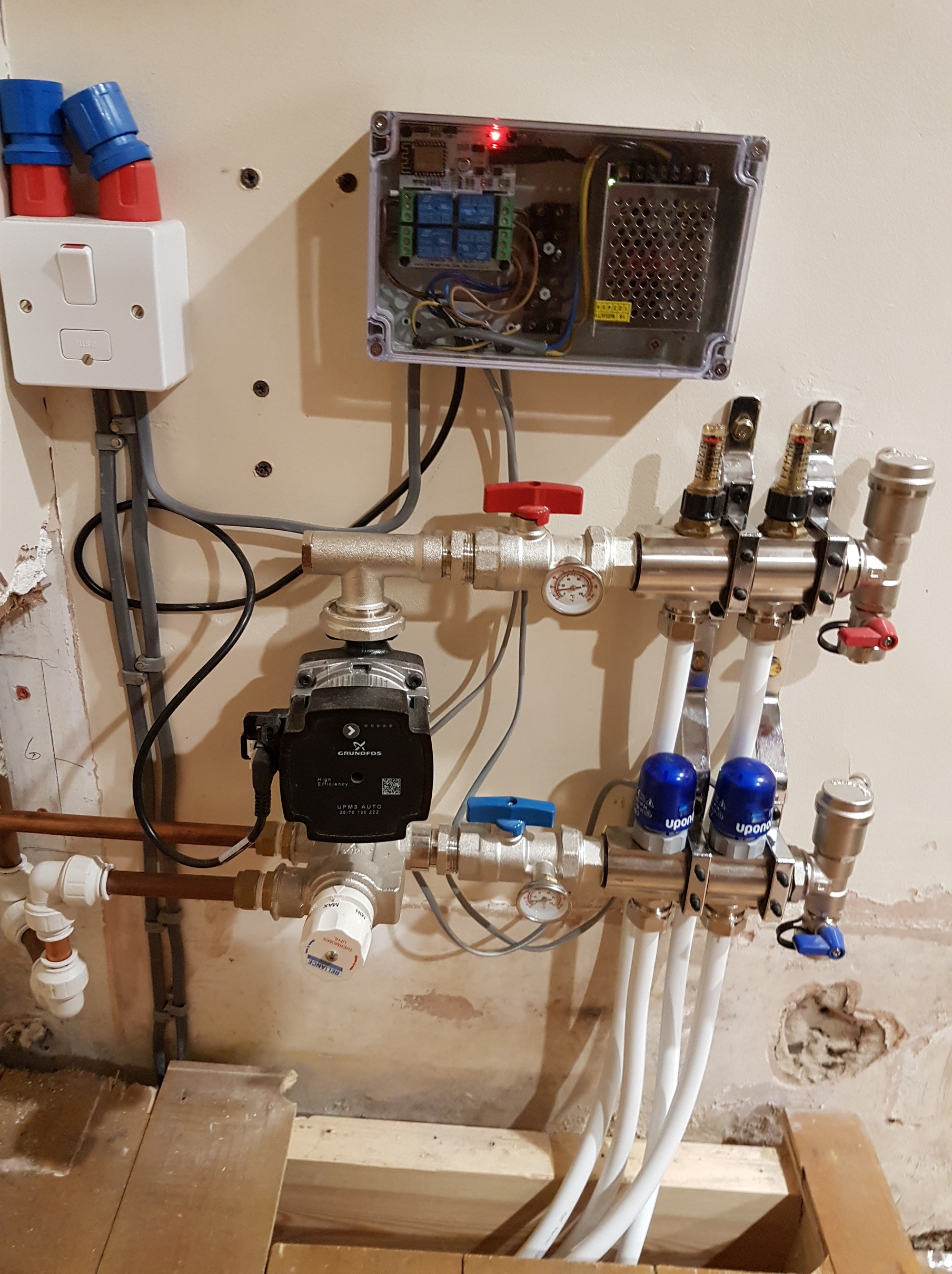
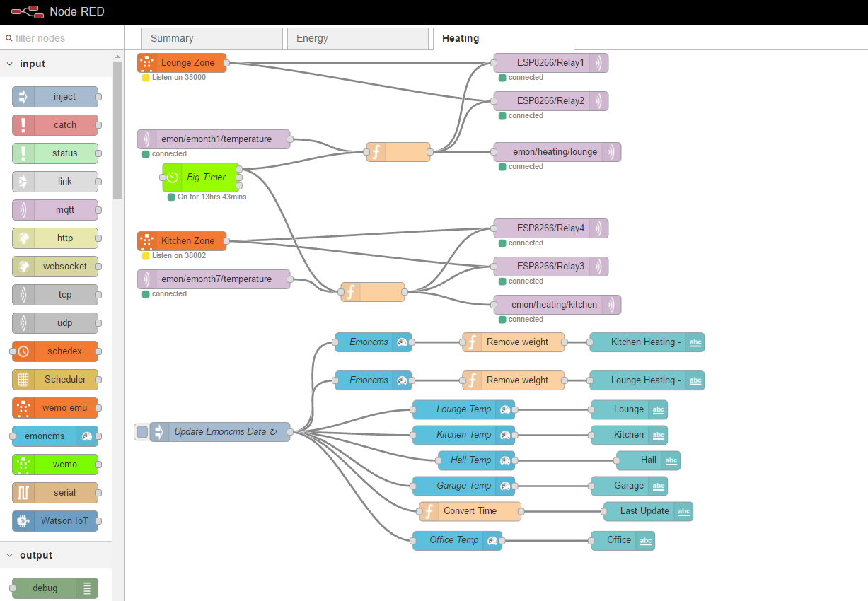
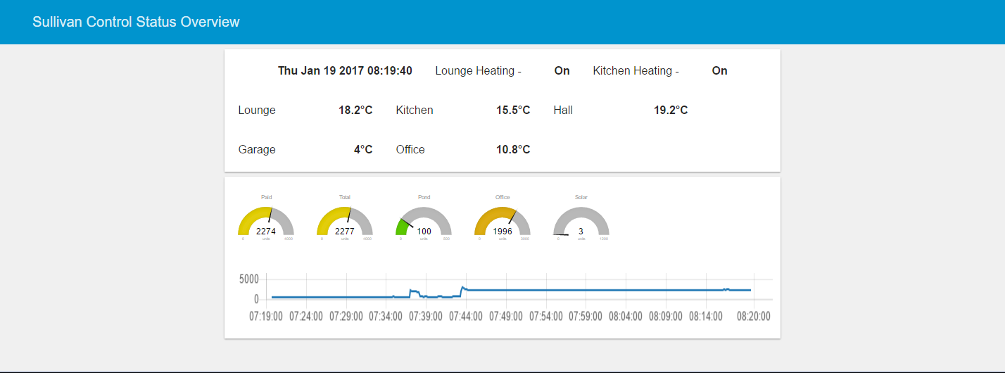
Ok so my version of this (first time ESP8266 & PlatformIO so a little bit pleased :slight_smile:). In all cases where I refer to Node-RED substitute your control system of choice. Differences:

  • Fixed IP (more easily found on network!) comment out the lines if you want a DHCP IP
  • I have used a separate topic for each relay rather than parse the payload.
  • Payload of 1 or 0 switches the relay
  • Relay subscribes to an MQTT heartbeat (in this case created by Node-RED) and sends a response back. This partially solves the two issues above (but see below).
  • The topics etc are defined as constants so easily changed
  • Initialise all relays to LOW

What I have not worked out how to do, and actually have no idea how to in C++, is use the heartbeat message to set a timer off, that if not reset, would set all relays to safe.

I’m not currently sending back a status message for the relays as doing this just after the relay is set is rather pointless (other than showing it was set). What is actually required is the state of the relay to be stored in a variable as it is set. This then could be returned (instead of just a 1) as a status message for Node-RED to act on (for instance compare returned state with required state).

If you get in the position where the relay loses connection to Node-RED, all the relays would then be set to safe, the status message that is sent when the connection is restored, would indicate all relays are off which may not be what the flow expects so can issue an appropriate command. Equally, if the relay has lost power, it will come up and report this in the status so again Node-RED knows to send the appropriate commands.

I know what I want to do but currently have reached the limit of my C++. If anyone feels like helping a poor newbie C++ programmer…

#include <ESP8266WiFi.h>
#include <PubSubClient.h>

//enironment setup
const char* ssid = "xxx";
const char* password = "xxx";
const char* mqtt_server = "192.168.0.1";

//MQTT Topics
const char* MQTTdeviceIDStr = "HeatingControl";
const char* HeartBeat = "nodered/heartbeat";
const char* LinkHeartBeat = "HeatingControlStatus/Status";
const char* Relay1Cmd = "HeatingControl/Cmd/Relay1";
const char* Relay2Cmd = "HeatingControl/Cmd/Relay2";
const char* Relay3Cmd = "HeatingControl/Cmd/Relay3";
const char* Relay4Cmd = "HeatingControl/Cmd/Relay4";

// these 3 lines for a fixed IP-address
IPAddress ip(192, 168, 7, 153);
IPAddress gateway(192, 168, 7, 25);
IPAddress subnet(255, 255, 255, 0);

WiFiClient espClient;
PubSubClient client(espClient);

void setup_wifi(){

  delay(10);
  // We start by connecting to a WiFi network
  Serial.println();
  Serial.print("Connecting to ");
  Serial.println(ssid);

  WiFi.mode(WIFI_STA);
  WiFi.hostname(MQTTdeviceIDStr);      // DHCP Hostname (useful for finding device for static lease)
  WiFi.config(ip, gateway, subnet);  // (DNS not required)
  WiFi.begin(ssid, password);

  while (WiFi.status() != WL_CONNECTED) {
    delay(500);
    Serial.print(".");
  }

  Serial.println("");
  Serial.println("WiFi connected");
  Serial.println("IP address: ");
  Serial.println(WiFi.localIP());
}

void callback(char* topic, byte* payload, unsigned int length) {
  Serial.print("Message arrived [");
  Serial.print(topic);
  Serial.print("] ");
  for (int i = 0; i < length; i++) {
    Serial.print((char)payload[i]);
  }

  int payloadi = (int)payload[0] - 48; //need to subtract 48 as chr 0 = int 48!

  // This looks to see which topic sent the message and outputs to the appropriate pin.
  if ((strcmp(topic, Relay1Cmd) == 0)) {
    digitalWrite(12, payloadi);
  } else if ((strcmp(topic, Relay2Cmd) == 0)) {
    digitalWrite(13, payloadi);
  } else if ((strcmp(topic, Relay3Cmd) == 0)) {
    digitalWrite(14, payloadi);
  } else if ((strcmp(topic, Relay4Cmd) == 0)) {
    digitalWrite(16, payloadi);
  } else if ((strcmp(topic, HeartBeat) == 0)) {
    client.publish(LinkHeartBeat, "1");
  } else {
    Serial.print("Bad Message");
  }

  Serial.println();
}

void reconnect() {
  // Loop until we're reconnected
  while (!client.connected()) {
    Serial.print("Attempting MQTT connection...");
    // Attempt to connect
    if (client.connect(MQTTdeviceIDStr)) {
      Serial.println(" MQTT connected");
      // Once connected, publish an announcement...
      client.publish(LinkHeartBeat, "1");
      // ... and resubscribe
      client.subscribe(HeartBeat);
      client.subscribe(Relay1Cmd);
      client.subscribe(Relay2Cmd);
      client.subscribe(Relay3Cmd);
      client.subscribe(Relay4Cmd);
    }
    else {
      Serial.print("failed, rc=");
      Serial.print(client.state());
      Serial.println(" try again in 5 seconds");
      // Wait 5 seconds before retrying
      delay(5000);
    }
  }
}

void setup() {

  pinMode(12,OUTPUT), pinMode(13,OUTPUT),pinMode(14,OUTPUT),pinMode(16,OUTPUT);
  // ensure all relays are off to LOW - assumed safe
  digitalWrite(12, LOW);
  digitalWrite(13, LOW);
  digitalWrite(14, LOW);
  digitalWrite(16, LOW);
  Serial.begin(115200);
  setup_wifi();
  client.setServer(mqtt_server, 1883);
  client.setCallback(callback);
  reconnect();
}

void loop() {

  if (!client.connected()) {
    reconnect();
  }
  client.loop();
}


Brian,

Take a look at the Ticker library. You can set up timers that will come back to you when the time has elapsed.

#include <Ticker.h>

So create an instance of a Ticker

Ticker Watchdog;

Define a routine called for example arewestilllive () which checks on a global variable, let’s say MQTTtickle; MQTTtickle is set to true whenever the topic you are subscribing to for the watchdog is received.

Then in your setup code so something like

Watchdog.attach (xx, arewestilllive); xx seconds ticker to call the routine

In the arewestilllive routine check on the MQTTtickle global variable, if it is false you haven’t had an MQTT message in time, so set all your relays to off. And always set the global variable to false before you leave the routine.

Obviously you need to be careful to make sure the arewestilllive routine isn’t called too quickly, so I’d make it run at say at least 3 times the interval you expect the MQTT watchdog message to arrive at.

Even then you may be in trouble. Image that there’s been a power failure - how long does it take your router to come back to life. With mine it can take several minutes, so you need to take this into account as well as any other failure or partial failure.

Obviously depends on what you are doing with your ESP8266 but for me I want the devices to work independently and report what’s going on to emoncms etc. rather than having the control logic in node-red/MQTT and the ESP being simply dumb remote switch. Important if you are trying to have them control say the temperature in an outhouse above freezing. The last thing you want to happen is that they turn off because your Pi is having a fit, or comms has failed, e.g. router malfunction.

Having said that, I’m sure you’ll be able to get the Ticker library to do what you want.

Simon

PS Ticker is also useful to get things done on the ESP which could cause the ESP watchdog to trip, so breaking things up into short simple routines run from the timers is a great way to make sure you don’t fall foul of that one.

I’ve never used the ESP8266, nor Patformio, but all that looks like standard Arduino library to me, therefore you can probably do it in exactly the same way as on the emonTx, Robin’s diverter,…
But you’ll need to test this (and no doubt prove me wrong!).

When you want to set the timer, you record the time now with a call to millis( ). That gets the time in milliseconds.
You add to that the time you want to delay for, and store this new (later) time.
You then carry on and do all the things you need to do in the loop.

Then you need to read the time and see if it’s time to do the thing you’re waiting for. In fact, you’ll probably do this just before you set the timer, because you want to have timed events repeating indefinitely.
So you read the time now, and compare it with the time you saved. If it’s less (earlier) you carry on with what you were doing. If it’s equal or later, you do your timed event, then (most likely) set the timer again to a new later time. And then carry on with the other stuff.

There’s a fairly erudite explanation and code example here: Arduino Playground - HomePage

I’m so glad to see that my original post has generated so much excitement and interest so here are my latest updates on my own solution.

Firstly I’m a novice in all areas but have now got a working underfloor heating control system that has a timer that comes on at selectable times of day. I can have ALEXA turn on my heating using the Node Red add-on and I have a pair of Thermostats to turn off each Zone when temperature reaches the set point.

I have not altered my original code. Instead I have used Node Red which is so easy to use and change within seconds and so far has worked for 2 months without any issues.

Here are a few pictures of the install and a screenshot of my Node Red code for those that are interested.

I have also used the Node-Red UI to monitor the whole system as well as inputs from my Emoncms installation.

All questions welcomed.

Alan

1 Like

Hi @powerman, Looks great. 3 questions:

  1. what is the enclosure
  2. What are you using to power the Linknode?
  3. What is the ‘big timer’ in Node-RED?

@Bramco Awesome. Just what I needed and so simple :smile:. To use it, I have added in

  Watchdog.attach (120, AreWeStillAlive);

to the MQTT callback. It is called every time the callback fires. Does using it in this way mean the timer is simply reset? I’m not wanting to create something that is leaking memory! It certainly looks like it does.

In terms of the delay, the idea is for a solid fallback to a safe state for the relay. What the safe state is, is up to the user. If it is more important that the outhouse is heated than the heater is on for too long then that is your safe state.

Hi Brian,

I obviously wasn’t as eloquent as the reference Robert gave!!

Anyway, you only need to call the attach once. Do this in your setup code.

Then the routine you have attached is called once every xx seconds forever. That would be 120 in your code above. So no need to keep calling the attach. In fact in situations where you want to do this you should call detach to detach any routines before doing another attach.

If you call it every time the MQTT call returns you will soon run out of resources!!

And, you know you keep saying you aren’t any good at C++, you seem to be doing fine - good enough to get things like this going without having to be an expert coder. What I would suggest you do is to spend some time looking at the esp8266 libraries and the examples https://github.com/esp8266/Arduino/tree/master/libraries. The specific one for the Ticker library is at https://github.com/esp8266/Arduino/tree/master/libraries/Ticker

And finally on the safe state, the safe state for managing the heater in the outhouse is that my ESP does it without any comms from another system, so it won’t default to ‘on’. It’s normal operation is to manage to the set points without having any comms from outside. Of course it reports what temperature it is and whether the heater is on or off but it doesn’t default to either on or off. Which is to my mind a much better control strategy, i.e. putting the control algorithm in the device doing the controlling.

Simon

Simon - you were posting while I was typing!

Actually I though what you offered was more elegant (Robert, yours was helpful though :smile:). Basically a single line of code.

I’ve done lots of coding, learnt and then worked as a Software Engineer with ADA in the late 80’s and 90’s and I’ve done quite a bit of PERL in the past and VBA. It is the constructs I am unfamiliar with and the libraries available.[quote=“Bramco, post:48, topic:2212”]
putting the control algorithm in the device doing the controlling.
[/quote]
I’m more inclined to have dumb devices that just do what they are told so I can change the behaviour remotely YMMV :wink: .

Back to the problem in hand. Ok so if I call the attach in the setup, the keep alive routine will simply trigger approximately every XX seconds. So it needs to trigger twice to go to safe; once to set a status to false and a second time to see if that status has been reset (by the callback). Logic is that if no callback has run, no MQTT message has been received so there is no control mechanism in place so default to safe.

All I need now is to sort out the status message so the controller knows the state of the relays (which will be sent after every heartbeat from the controller) and it can act accordingly.

Never been accused as being elegant before - result!! :grin:

And ADA that’s serious stuff. We once had to do FMEA analysis for some systems we were developing. In the end we managed to have all the failure modes and effects in hardware - phew! It would have been a nightmare to do it on the software and software environment. We were doing Object-oriented design in a CASE tool with snippets of code for each method, then generating C++ and cross compiling into C to go onto 8051s. Yes 8051s… Used to talk about this at conferences and no-one believed us until we showed them.

Simon

Hi,

  1. Purchased a clear top plastic box off Amazon £10
    
  2. I purchased a 5V PSU with mains input designed for lights off Amazon. Works a treat
    
  3. The Timer in Node-RED puts out a 1 state if the time of day falls in between set points and then I use a function to compare temp from thermostat and fixed value to send relay MQTT command to the relay board
    

Function code

Hope that helps…

1 Like

Thanks. Found quite easily on Amazon. What size of PS did you go for. 3A or just a 2A?

I had not realised bigtimer was a node from Pete Scargill. Thanks, that’ll be useful.

Cheers

I used the 2A which runs cold and no issues so far.
Alan

1 Like

There is a new alternative from Sonoff.

See the review from Pete Scargill → http://tech.scargill.net/sonoff-4ch-4-channel-mains-control/

Also there’s a link in there to some great software from Theo Arendts which covers all the Sonoff variants with OTA.

One of the great things about this unit is that one of the unused GPIOs is broken out on the header alongside the pins for programming. So you can attach a set of DS18B20s onto there for reading temperatures. Or anything else of course.

I’ll be replacing my homebrew heat bank controller with one of these as soon as it lands.

Simon

One thing to note is that the Linknode allows connection either NC or NO. It looks like the Sonoff doesn’t and I’d assume it connects as NO.

Hi…i am a new user here. In my case I am able to control the relays only via the LinkSprite APP over the internet. No local access to the relays it would seem despite the IP address being available and all normal normal ports for http tried.Size as you can see is about 3 inches square using the AA battery for comparison.

printed circuit board