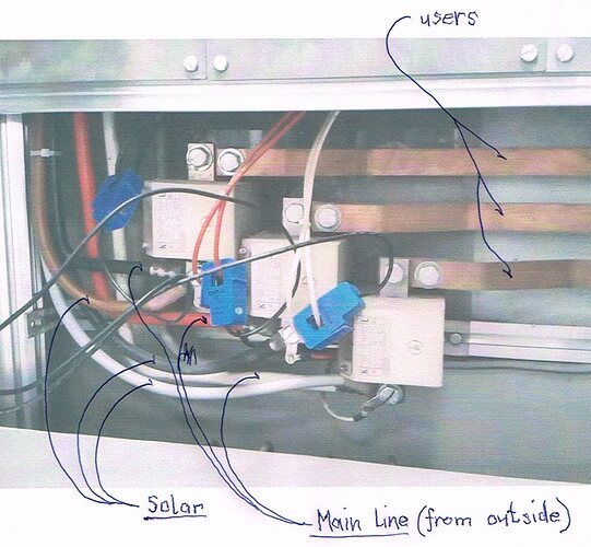
No, the SCT13 are direct before the energymeter from the power company.
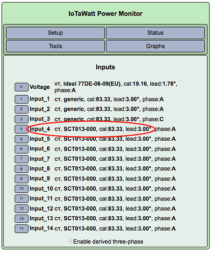
Where can I get this 3° shift factor and if it is plus or minus?
Ok, I think I still have not quite understood your setup. What kind of energy meter is it? Does it also count the exported solar energy (two way meter)? In the case of exporting energy the power would be negative, is that the case? Is the IoTaWatt configured to measure negative numbers?
Can you please share some more details about that current transformer, please?
Is it a CT connected to IotaWatt?
For clarification: An old picture with the predecessor of IotaWatt.
And here an other explanation:
You can’t see the 3 CT’s from solar, they are clipsed close to the meter (higher up).
This is the old configuration, it gave me a good result on solar but I was not able to get a predictable value on ‘use’.
On the actual configutation I clipsed the CT’s to the main line. Now I have to make a calculation for ‘use’ as ‘solar’ and ‘use’ are on the same lines.
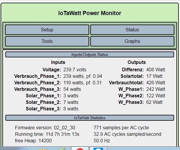
And the status, it’s middle of the night, no sun.
I have to wait for results to compare it with the meter.
Thanks, now I got it. But I think it doesn’t make sence to split it into an other forum. I hope that’s o.K.
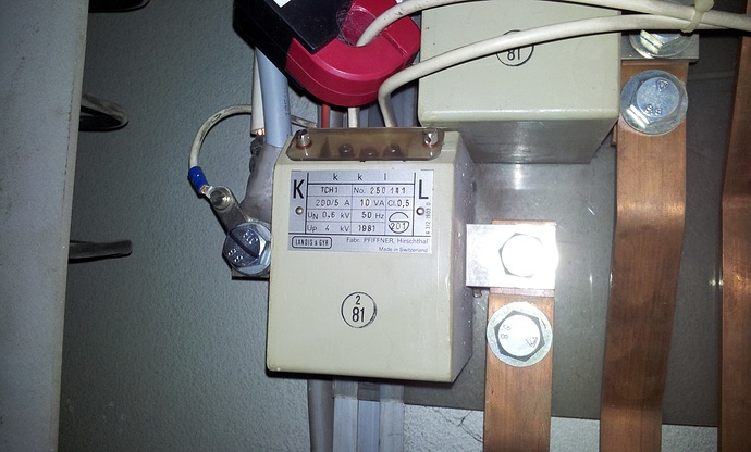
Thanks for the pictures, that makes it a bit clearer. So you are measuring the secondary current of the installed 200/5A current transformer. Are these current transformers used for the official meter from the electricity company or for what purpose are they? If not where is the officially meter located?
It looks like Solar and Mains are connected together just before the current transformer which are measuring the consumption of the users, is it correct?
If you have 100 A YHDC c.t’s on the secondary circuit of a 5 A c.t, you must expect the result to be not accurate. Although the YHDC does work below 5 A, the accuracy is not specified below 5 A and the errors will increase significantly as the current gets smaller.
Unfortunately, I cannot think of a 5 A primary split-core c.t. that I can recommend. The best I can think of is a Wattcore WC1 25 A : 100 mA, which will give you 20 mA (40% of full scale for an emonTx or emonPi) at 5 A:
This perhaps? (Magnelab)
100A:5A also available in 200 and 300 Amp versions. Wire window is 0.94 inches
The SCT006 from the shop should also be good as long as the secondary current does not go higher than 16 A, or not?
Or if possible, it would probably be better to skip the current transformer at all and meausure with 200A CTs on the primary side: 200A max clip-on current sensor CT - Shop | OpenEnergyMonitor
No, Bill, he’s using the meter c.t’s as interposing c.t’s, their secondary current is 5 A, so we need a c.t. with (ideally) a 5 A primary current capability, not secondary. Unless of course you were thinking of putting the c.t.'s on the busbars.
'Twas exactly what I was thinking. I should’ve specified that.
Not, I’m afraid. At 5 A primary current, the SCT006 will give only 6.25 mA, so much poorer than the Wattcore.
Going around the meter c.t’s is a possibility, if there is room between the busbars to get them in.
OK, here’s another suggestion…
Magnelab SCT0750-000 (unburdened variant) with a 1470Ω user supplied burden to yield a 5A rating. (1.47KΩ is a standard value)
Burden value derived from
Relevant excerpt from the second document:
Q
Can an SCT0750-005 Current Sensor be used on a 30, 50 or even 200 Amp circuit?
A
Magnelab SCT 0750 Current Transformers can function safely from zero to
200 Amps. A 5 Amp unit will have an output of 0.333 Volt at 5 Amps and the
same unit used at 200 Amps will have an ideal output of 13.33 Volts. The
temperature rise at 200 Amps will be only a few degrees due to low current in
the secondary winding. Therefore, an SCT 0750-005 (5 Amp unit) could be used
at 200 Amps since the core does not saturate and the temperature increase is
minimal.
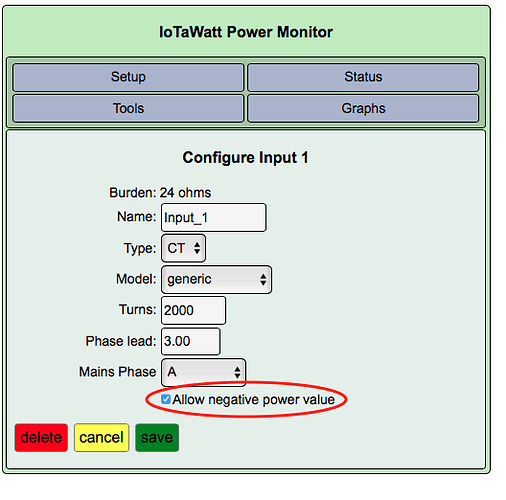
That looks right. Just be sure the “allow negative power values” are checked for the mains.
I’d really encourage you to follow up in the IoTaWatt forum.
Yes, this cables are connected direct to the meter.
Yes, there is a separate meter for solar and for user (with the current transformer).
That’s probably a good decision, so you are not longer measuring over the 200/5A CT’s. Are you sure your current does not exceed 83 A? That’s the maximum possible current with the SCT013 and the burden resistor in IotaWatt IMHO.
Assuming you feed all solar energy into the grid without self consumption (no two way direction meter) and “allow negative power values” are checked for the mains like @overeasy did mention, your calculation seems to be correct. Keep us updated about the results ![]()
I have now measured 1 month again. The measurement of the solar part is almost 100%. But the measurement of the consumer does not correspond with the electricity meter of the electricity plant at all. IotaWatt measures about 50% more energy than the meter from the power company.
Today I made a try. I switched off the solar system and started a 15 kW compressor. IotaWatt then displayed a power factor of 0.80. Then I switched the solar system on again (about 5 kW power) without compressor and received a Pf 0.99 . Then solar and compressor together. IotaWatt then displayed no Pf .
I measure with a VT with Derived Reference. Sensor installation according to type 2.
I suspect that the power factor is not measured correctly on two phases. I do not know what I can do.
That’s an interesting finding. There are some API’s that return the phase shift between VT and one of the connected current transformers. They could give some insights into what is actually happening. But to be honest, I’m running out of ideas. Please register at community.iotawatt.com. This allows you to get help from the inventor of Iotawatt.
