Take a look at the Sparkfun website.
You can add a length of 50 Ω co-ax and terminate that at the ground plane, then the antenna length is ¼ λ from the ground plane.
Take a look at the Sparkfun website.
You can add a length of 50 Ω co-ax and terminate that at the ground plane, then the antenna length is ¼ λ from the ground plane.
Oooh, I never even considered a dipole Robert…
Paul
Ah yes, Sorry missed that for 433MHz. Yes I have a TX but I was thinking more of the base station RFMPi board. This is currently mounted on a Orange Pi Zero so a fixed antenna would not be an issue. I don’t think I need to go to a ground plane as well.
The ground plane will help at both transmitting and receiving ends of the link.
Hi Robert, yes I get that. I just do not need that much improvement. The solid antenna on the receiving end should be just what I need. Also it is currently mounted on a wall which makes a ground plane a little tricky!
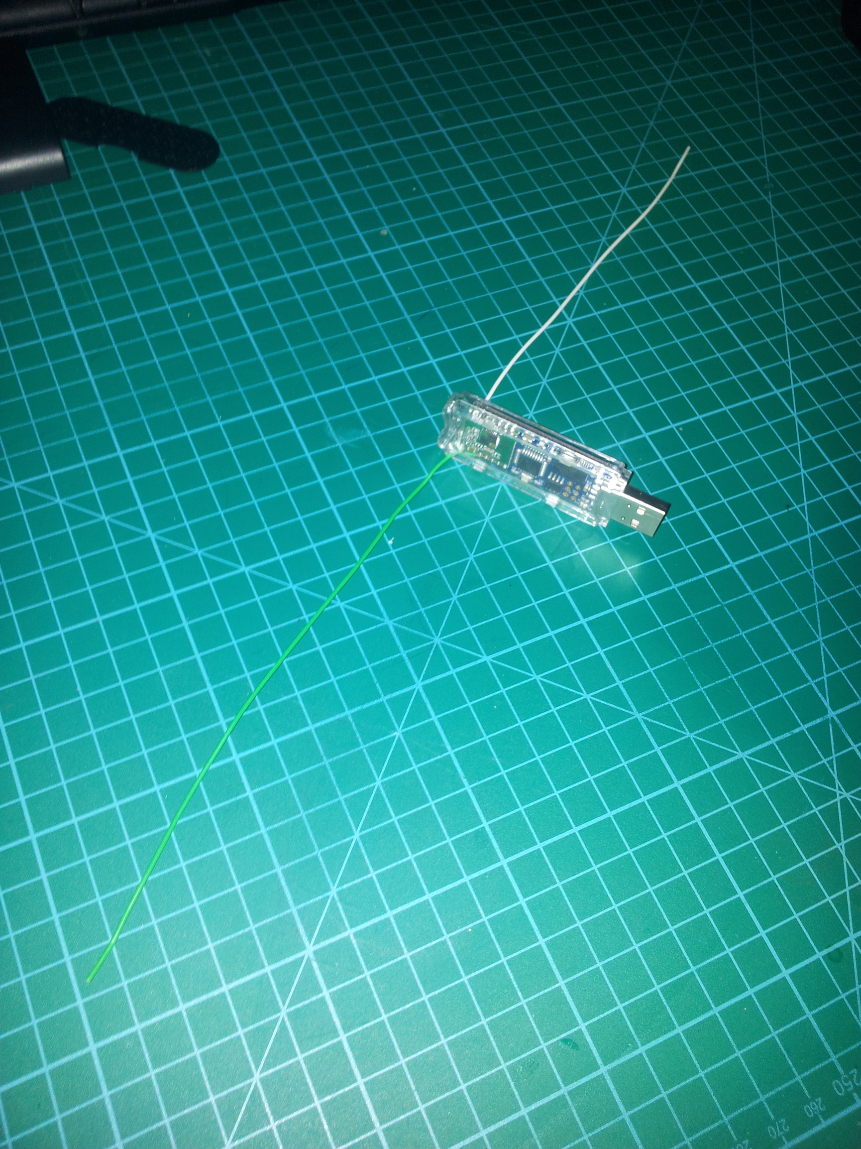
Adding a second wire of the same length to a gnd track near the existing antenna wire would work really well as a dipole. I had massive gains when I played with this on a JeeLink a couple of years back, a few days ago I went to add a link to a previous thread here as I had posted a picture back then but the pic’s no longer attached (“weak signal?” on old forum), but I’ve just found a local copy.
It’s just simple single solid core bread-boarding link wire, I have since rolled this method out on most of my emonTH’s, and rfm2pi’s with great results. plus the wires are thin enough to be discrete, especially when the wires can also be color coded to their surroundings too.
I’ve also discovered that the antenna wire and ground plane wire are not that fussy about positioning, I have one rfm2pi on a Pi in a small case and both wires are coiled inside, one above and one below the board and even that gives better reception than the original multi-core antenna wire without a ground plane.
I’d read about ‘coiling’ antennas elsewhere, but dismissed it as I couldn’t reconcile the supporting theory…
…but it’s many years since I studied RF, and I’ve forgot more than I learnt!
Paul
Oh no, I wasn’t suggesting I had done anything technically advanced, quite the opposite, I was just saying l’ve “tucked the wires away” rather than having the antenna and ground wires fully extended in opposing directions, and still getting good results.
The only “gotcha” here is a 5/8th wave antenna needs a matching section at the feedpoint. e.g. a tapped coil.
Found some video clips I’d forgotten I made.
The ground plane doesn’t necessarily need to be metallic, just conductive.
As can be seen in the first video clip below, an anti-static bag works quite well.
In this clip, we see that it works even if the ground plane is simply adjacent to the Pi vice underneath it.