But… replacing the CAT 5 antenna with a 82mm length of 2.5mm solid copper (13A mains cable), I now get the following results, with both transmitter & receiver in exactly same positions;
I’d be worried about pulling the pad off the PCB should that get caught in clothing or a duster, if it’s not otherwise supported.
You could still try adding a ground plane - it should give you a few more dBs of signal. It doesn’t have to be a solid sheet, a conducting mesh or even 4 more pieces of 2.5 mm^2 radiating outwards from the base of the whip antenna would help.
Yes. For the past 2 years it’s provided about 60db as the base station was about 4mtrs away, but the weakness has been exposed by moving the base to another room.
I did think about that, but its supported from lateral movement by the case (protrudes through a hole!), and it’s wall mounted at about 2mtrs high in my garage, so should be ok.
I’ll try adding a ground plane to improve ss further, and good point about adding one to the base station too.
The main beam radiates above the ground plane, at 45° but less as the ground plane improves, so you want the transmitters and receiver to ideally be in the same plane, with the antenna ground planes parallel to that, or even better, inclined slightly down in the direction of the other end.
The radiation pattern is omnidirectional, i.e. a somewhat flattened toroid centred on the whip.
The signal strength is plotted looking broadside at the whip.
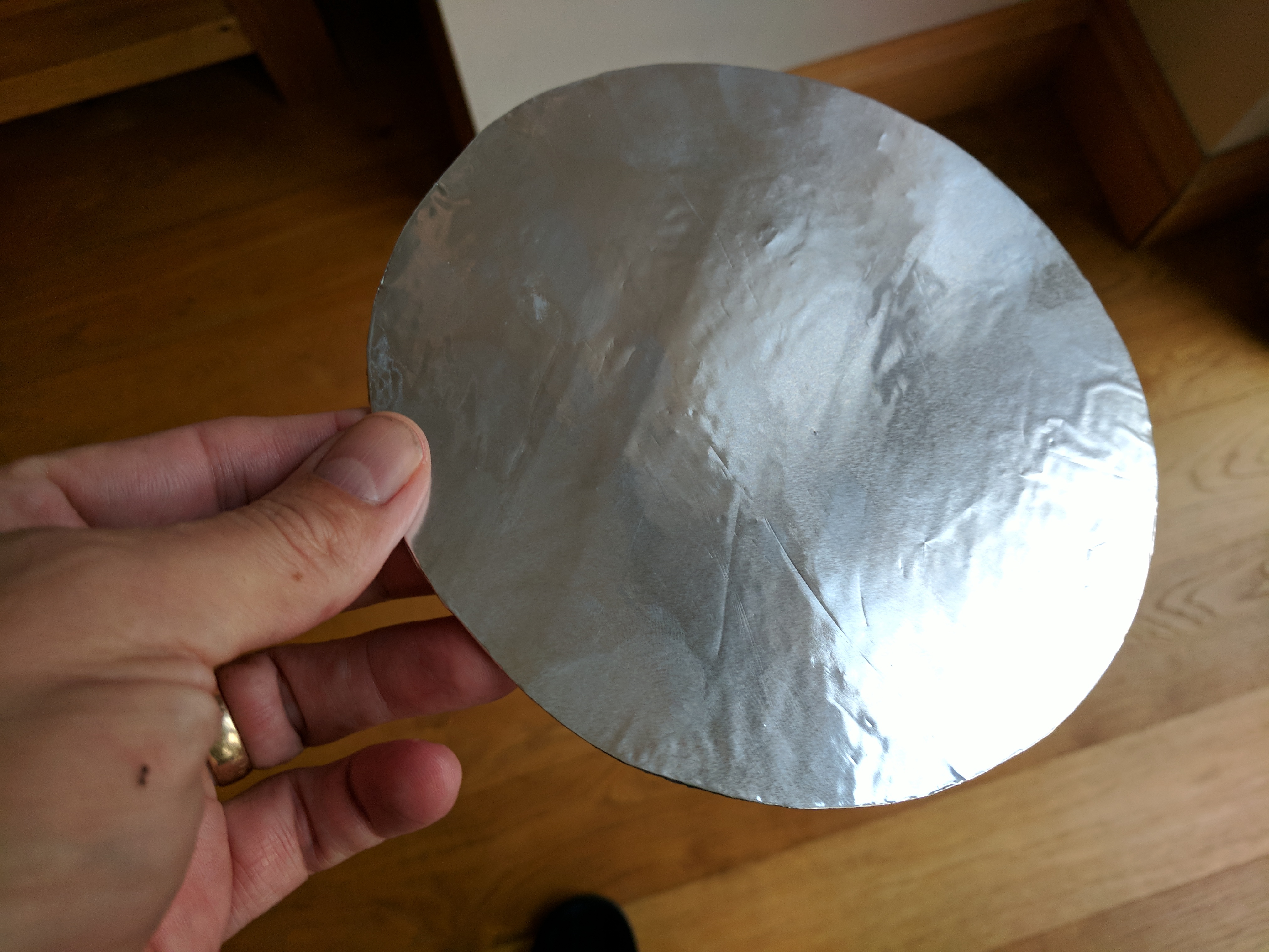
I made 2 ground planes earlier from 165mm diameter pieces of cardboard, and stuck aluminium foil to the uppermost surface (see image below).
I sat the emonTX on one (instead of the sheet of foil I tried yesterday), and also sat the Raspberry Pi base station on the other (no earth connection) and immediately saw yet further signal strength improvements, despite both units remaining in exactly same locations.
Measuring over a 2hr period, I now have;
Mean
Min
Max
Diff
Dev
npoints
-66.1
-72.0
-54.0
18.0
3.0
720
Which seems a big difference from the -81.8db mean average, which I had 2 days earlier.
No, just place the Pi on top of the disk so the antenna is centered in the circle - there are no electrical connections to the foil.
NOTE; I made it 165mm diameter because I understand that it’s radius should equal the antenna length. Which in my case it was 82mm (868MHz).
I assume that it would need to be 330mm diameter for a 433MHz system which has a 165mm antenna.
@Bill.Thomson contacted me earlier today, and sent me the below video that he took several weeks ago regarding the ground plane effect.
To set the scene, Bill’s emonTx is located about 75 feet from where the emonBase in the video clip is, and there are three walls between the two. Watch what happens to the RFM12 LED when he removes & replaces the aluminium foil from the emonTX…
I was thinking more of the connection to the PCB for the antenna. Straight down or a slight bend on the bottom of the wire and if so, does the bent part get included in the 82mm length?
I also wonder about putting a hole in the ground plane and putting the antenna through the hole and sitting it on the case.
My emonTX is in a bespoke case, which enables me to have the antenna vertical, however with a emonTX in a openenergymonitor case, it’s problematic to use a ground plane, unless you drill a small hole in the case, pass the antenna through, and lay the emonTX flat.
I think that I gave details for the 433MHz antenna in a post above.
Ah yes, Sorry missed that for 433MHz. Yes I have a TX but I was thinking more of the base station RFMPi board. This is currently mounted on a Orange Pi Zero so a fixed antenna would not be an issue. I don’t think I need to go to a ground plane as well.
Hi Robert, yes I get that. I just do not need that much improvement. The solid antenna on the receiving end should be just what I need. Also it is currently mounted on a wall which makes a ground plane a little tricky!