How quick is the emonTx V3?

Let me explain. I have a pump for the “black water” it is away from home and I do not have any way to know if it’s working or not apart getting the house flooded with “black water”… disgusting.
I was planning to use one of the 100A max clip-on current sensor CT to monitor the current absorbed by the pump.

Now the point is that as the pump is very powerfull it works for just seconds also I need to know how much power is consuming when it starts as well as when it’s working.
So here the question: how quickly the emonTx can sample the data? and get the spike?
can I have a “spike function” to tell me which was the maximum power absorption?
Let’s say is 3A over 5 seconds could be 6A for 1 second and then 2A for 4 sec… the average is 3A over 5 but is VERY different.

Can you help me?

M

If you have a maximum current of 6 A, then the 100 A CT is not the correct device to use if you need any form of accuracy, unless you can arrange several turns of wire for the primary winding of the transformer. But as you say the pump is very powerful, is 6 A the maximum current or were you only trying to explain inrush, because that is what we call the starting current of any electrical equipment. (6 A is only 4 kW even if it is 3-phase.) It would help if you could tell us the rating of the pump in amps or kilowatts, and the voltage, and whether it is single or three phase. Also, what type of starter does it have - DOL, star-delta, electronic soft-start?

How do you intend to display the power? If you are intending to use emoncms.org, then it will not be possible to do what you want because you are only allowed to post data every 10 s. But if you have your own server on which you run your own copy of emoncms, then you may post data as often as you wish.

The standard emonTx sketch averages the power/current over a period of 200 ms, but you can change that if you wish; and it pauses for 10 s between readings, but you can change that too. So provided the inrush lasts for longer than a 5 or 6 cycles, then it should be possible to record something close to the peak current. You will need to modify the standard sketch a little to do that.

The Atmega 328 processor on the emonTx can sample an analogue waveform every 104uS. So if your program can be running continuously, you should then be able to study the start-up behaviour of your pump in great detail.

If you store the data in a circular array, you could then include the data point(s) immediately before the pump starts to draw power. There would have to be some criteria for stopping the sampling process otherwise your one-shot data would very soon be overwritten.

“If you have a maximum current of 6 A, then the 100 A CT is not the correct device to use if you need any form of accuracy”
Well in Italy the standard household contract is 3kW on 220 so it means 13,64A maximum.
On the store there is no other sensor certified with the emonTx V3 apart that one.
What would you suggest?

“It would help if you could tell us the rating of the pump in amps or kilowatts, and the voltage, and whether it is single or three phase. Also, what type of starter does it have - DOL, star-delta, electronic soft-start?”
The pump is rated 1kW on 220V single phase.
It does not have soft start or similar. There is a 30microF condensator to handle the inrush/startup current.

“How do you intend to display the power?”
I’m ok to post the high level power to emoncms.org for global monitoring purposes but I can use even a local server for the detailed info.

“The standard emonTx sketch averages the power/current over a period of 200 ms, but you can change that if you wish; and it pauses for 10 s between readings, but you can change that too. So provided the inrush lasts for longer than a 5 or 6 cycles, then it should be possible to record something close to the peak current. You will need to modify the standard sketch a little to do that.”
I think even the standard should be good :slight_smile:
The points are:

  1. how fast will it be able to post to a local server?
  2. is it possible to post “quick” data to local server and “standard” data to emoncms.org?

This is good but I was not thinking to do a custom implementation but use the standard software as much as I can… in order not to get crazy with updates, fixes, etc…

Also I have to compute the time it takes to save the data do SD or other memory or post it to a service… it could slow down really a lot

That does not mean that there is no other suitable CT. There are two possible solutions:

  1. If your wiring allows it, you could use many turns of wire for the primary winding. 6 turns - 6 times through the CT - will give you a 16.66 A range, for example. Or if you cannot get 6 turns through, then increasing the value of the burden resistor will also help.

  2. Alternatively, you could use a different CT. I suggest you look at the Continental Control Systems and Sentran devices that we show on the EmonTx in North America page. The Sentran are the easiest to use with the emonTx, as it only means adding a resistor.

That means the running current will be a little less than 5.5 A, but the inrush current will be several times this - it might be as high as 50 A, but is more likely to be in the range 30 - 40 A. If you need to accurately record the peak (i.e. not clip it in the analogue electronics), the you’re going to need much more than 6 A as your maximum current. I suggest you start with our standard 100 A CT and see what you measure, and then if the peak is less than 50 A, use a 2-turns primary winding, less than 33 A - 3 turns, and so on.

As fast as you wish. If you measure for 10 half-cycles (100 ms), you can post every 5 cycles. Actually, it will probably be every 5½ or 6 cycles, because the software starts and ends the measurements as close as it can to a zero crossing.

It is possible, but it is not easy. You will need to modify the sketch so that it sends the data as two different nodes, and there is no provision for that, as far as I know, in JeeLib. It means using low level commands direct to the radio module. The software exists, attached to the 3-phase sketch on GitHub.

Your motor sounds very similarly sized to my pool pump, which is a 240V single phase 1.5HP motor. Mine typically draws about 1100W when everything is running normally. The capacitor you refer to is probably the starting cap. When that starts to fail, as mine did recently, you’ll find the motor intermittently stalls on start-up… it just sits there and hums and draws a lot of current for a worrying number of seconds and then eventually starts.

If I’m near it at the time, I can give it a flick and it starts right up. Experiments on a salvaged motor from a previous pump reveal it’ll happily run in either direction from that state, depending on which direction I flick it, so you really want to make sure you flick it in the right direction once it’s installed in the system.

All that lends itself nicely to early failure detection and reporting. My monitor now reports things like:

-------- Forwarded Message --------
Subject: Check pool pump
Date: Fri, 14 Oct 2016 16:00:11 +1000
From: xxx
To: xxx

Possible pool rotor lock event detected (3266W), timer 1 stopped

Regards,
Primary Server.

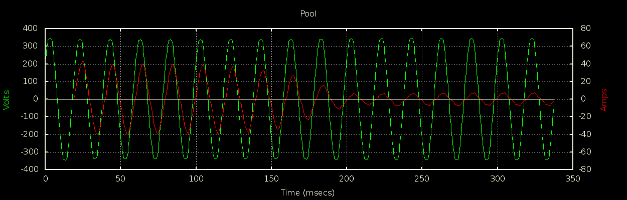
It no doubt varies from pump to pump and application to application, but to give you some idea of the startup current when everything is working normally, I initially assumed a 20A CT would be fine for a pump that uses about 5A once running, but it turns out it was clipping badly on startup. I replaced that with a 50A CT and you can see in the attached capture from my energy monitor that the first peak exceeds 40A. My CTs and energy monitor are not OEM based, so not directly translatable to what you’ll need, but I’ve included them to give you a feel for what my similarly sized pump looks like on start-up.

That’s about what I’d expect - it can be up to about 8 times the running current (but not as bad as a tungsten lamp at about 13 times!).
And it’s a fairly standard capacitor-start, capacitor-run motor. The capacitor and its winding provide a second phase to create a rotating magnetic field that the rotor latches on to. Without the capacitor - or enough capacitor - there’s not enough torque to overcome the friction, hence it sticks and draws the “locked rotor” current. If, @msavazzi, your motor rating plate gives a value for the locked rotor current, then that gives you your CT rating.

Yes, as the cap started to lose capacity, I was getting reports about once per week, which is about 1 in every 20 motor starts. I marked where a particular blade on the cooling fan was in relation to the body of motor, and sure enough, when it stuck, it always stuck in the same place… presumably the position of highest friction.