I wonder if this is a consequence of your BT6 being in the wrong location - or some other issue with your DHW tank?
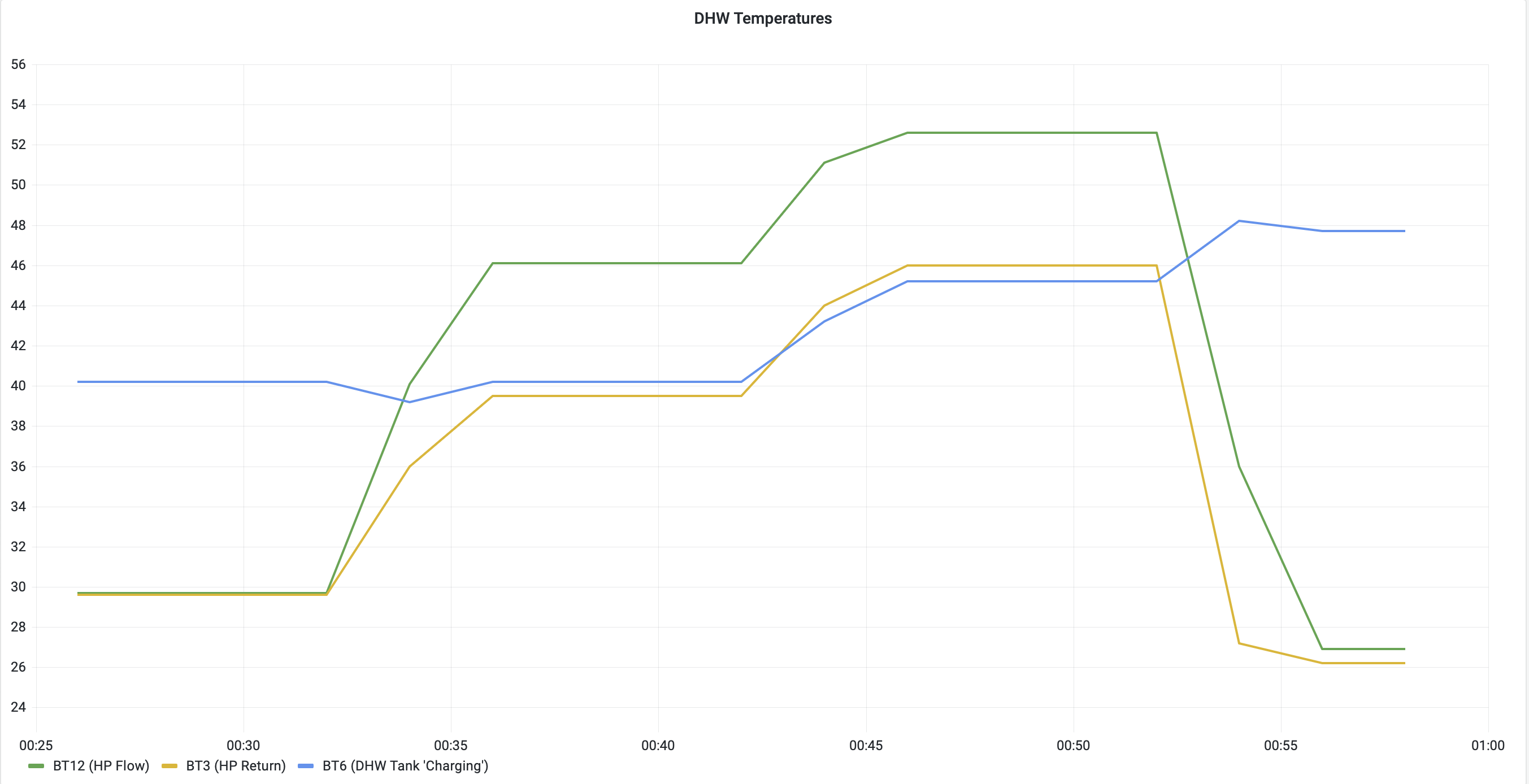
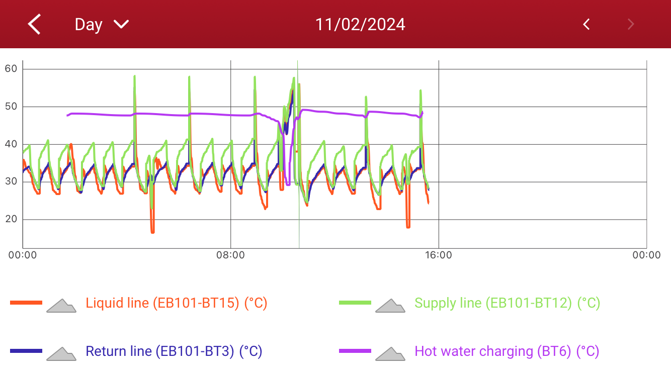
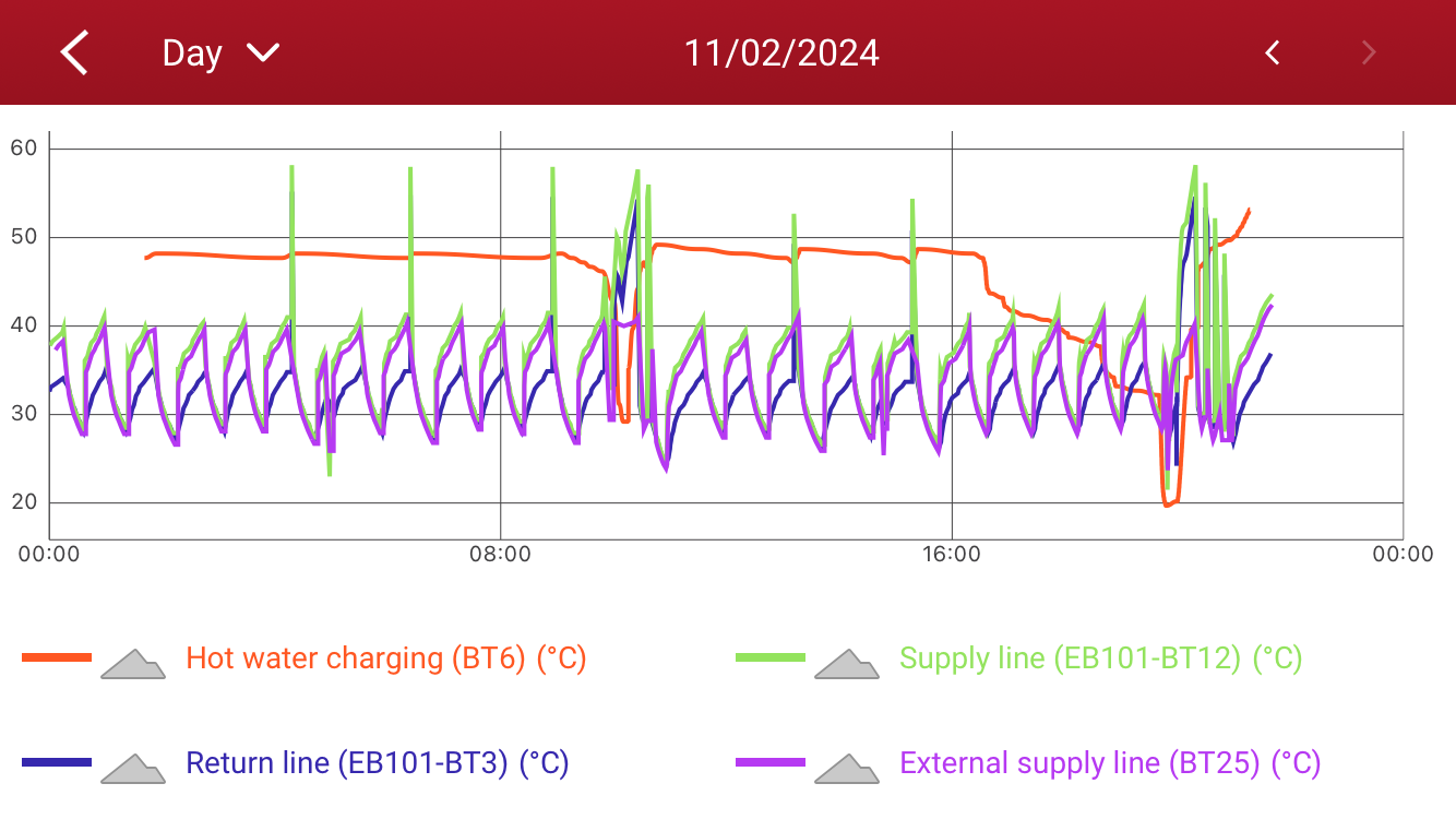
On my system, the Return temp (BT3) very closely matches the rise in BT6 (the DHW cylinder temp) - example of one of my DHW cycles here (note the graph is a bit ‘lumpy’ since I only grab the readings back from NIBE Uplink every 2 mins):
BT6 and BT3 rise together - they’re always within one degree of each other
BT12 (the Flow temp) is increased by the heat pump controller as BT3 (the Return temp) rises, to preserve the temperature difference and maintain the heat transfer to the DHW tank
It’s odd that your BT6 is showing a much lower temperature than BT3 while the tank is heating. The controller thinks it needs to keep heating the tank (based on BT6) but it’s increasing BT12 to maintain delta-T with BT3, pushing BT12 high and triggering the alarm.
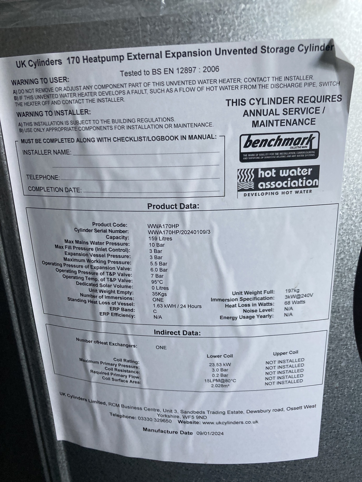
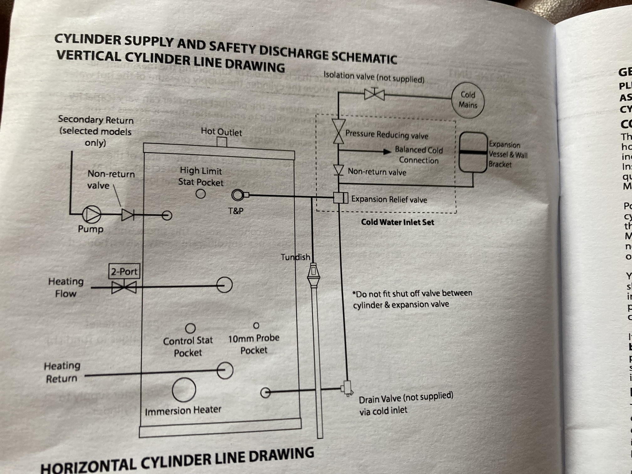
Could you post a photo of the white label to the left of the big red circular label on the DHW cylinder please? I’ve been looking at the UK Cylinders website but not managed to spot a model which matches yours - would be good to confirm that it actually is a ‘heat pump compatible’ one.
Ideally there’ll be a Product Code on there - something like “ESHPD2170”.
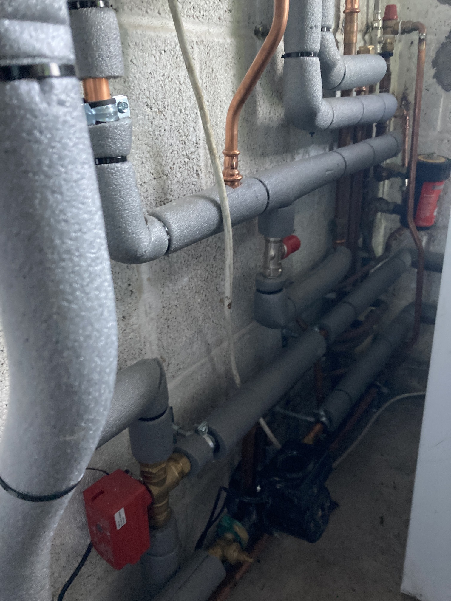
The pipe work seems to be quite complicated and I haven’t been able to figure out how the flows to and from the buffer are configured.
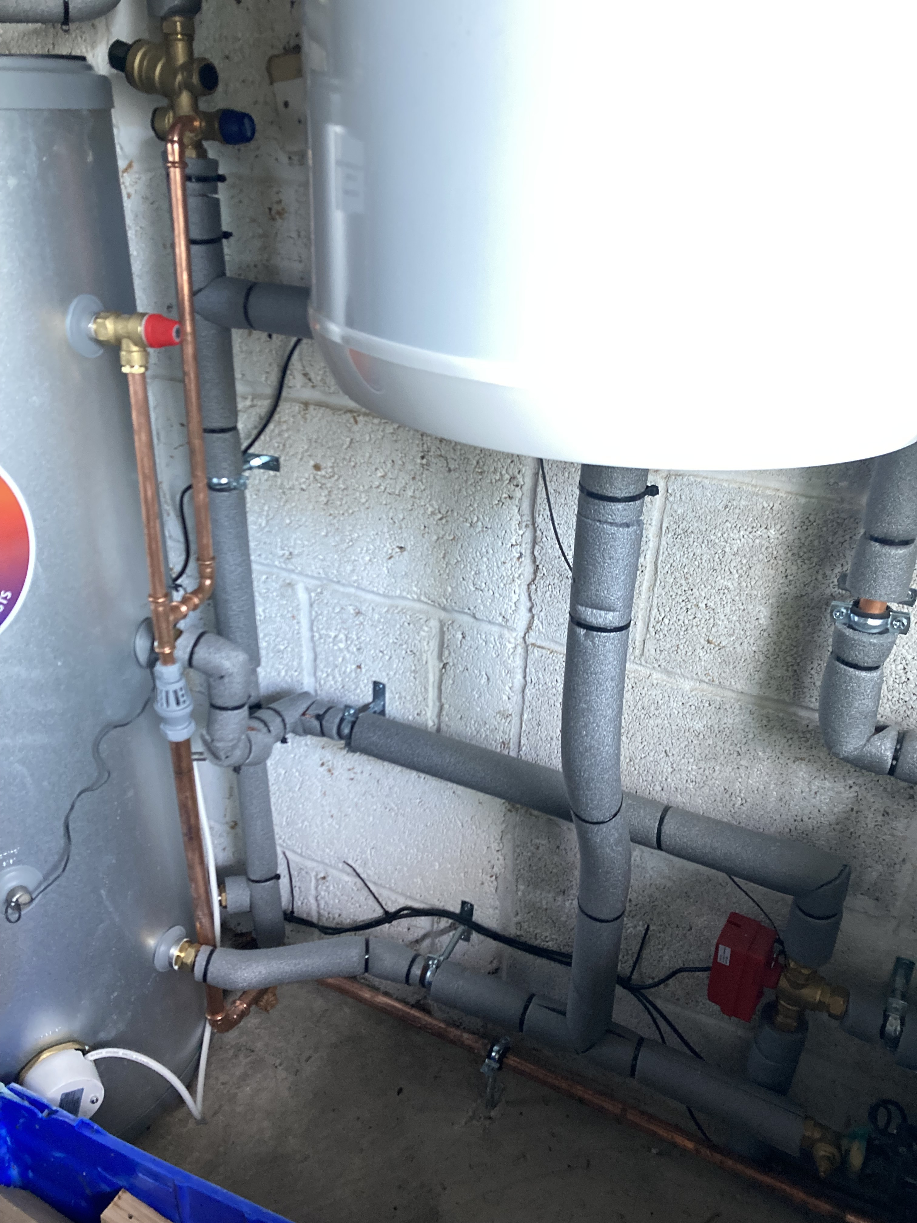
Here are some photos - couldn’t fit it all into one, so running from right to left, from where the heat pump pipes come inside the garage, towards the buffer, and then to the DHW cylinder.
Has the cycling stopped? I too suffer the same alarm, I also get a high condenser in alarm too. Always when charging hot water. I’ve not been able to figure it out yet but maybe this discussion will help me too
With regard to plumbing, it looks like flow goes into the cylinder around half way up and returns out the bottom. If that’s correct, it does means your BT6 probe is quite way from the charging coil which might contribute to some the things being observed.
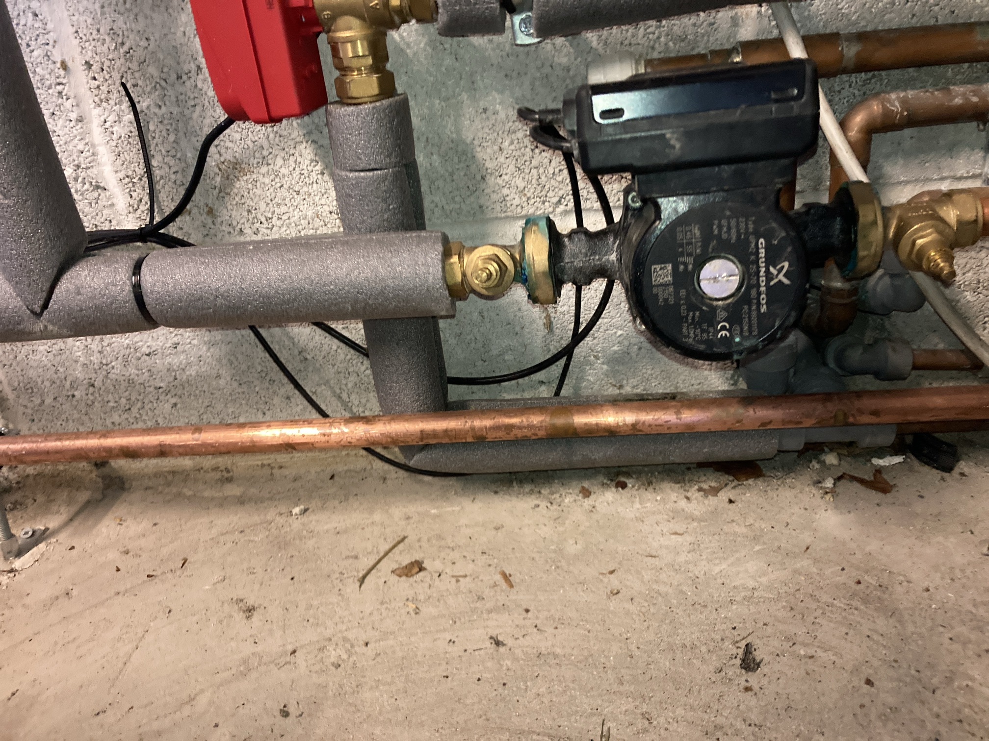
Your buffer flow should be isolated from the DHW tank via the red valve and it looks like the buffer return comes out the buffer tank downward and joins the return from the cylinder before hitting the charge pump and returning back to the heat pump.
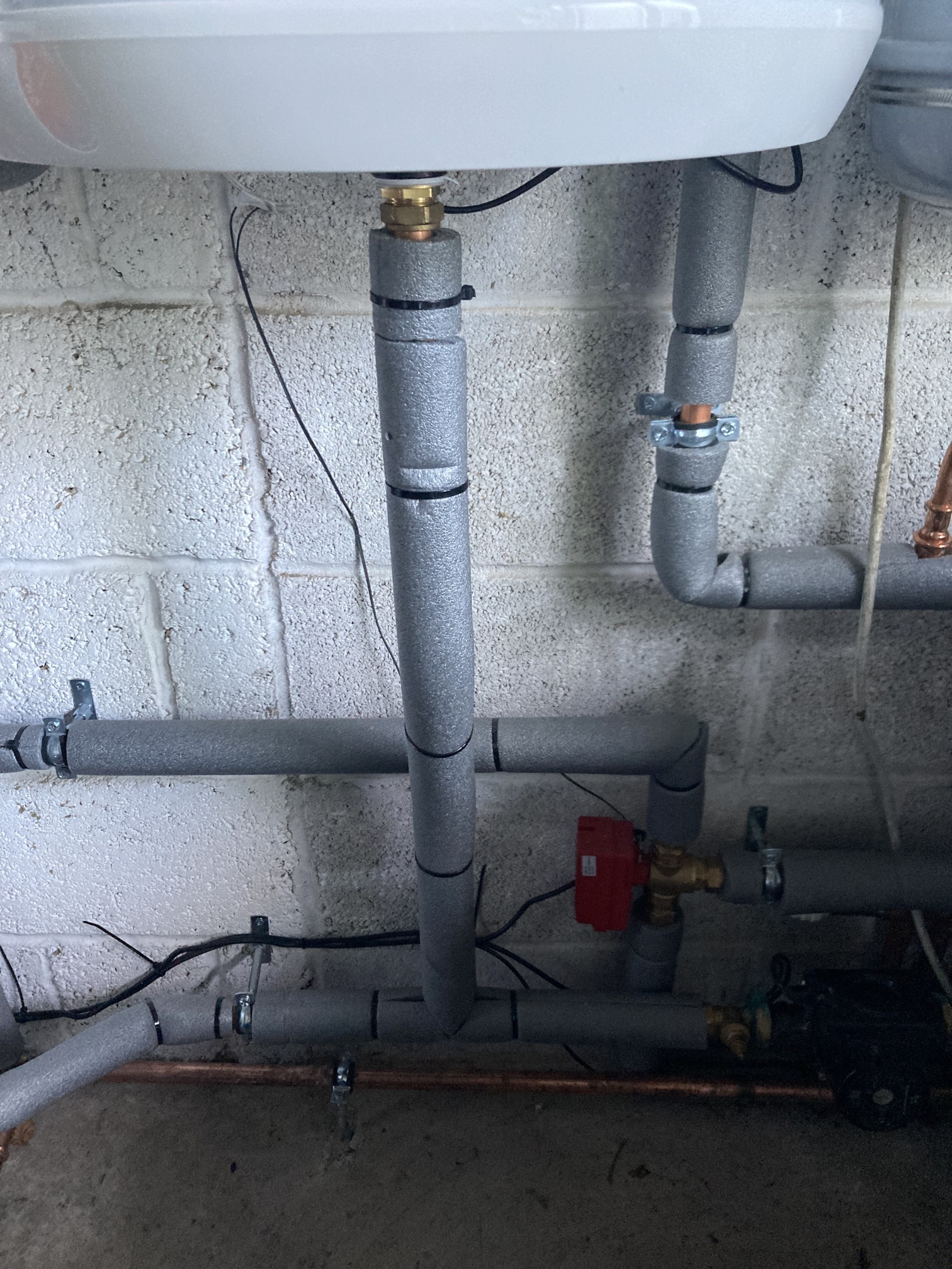
Out of interest, where does the pipe that goes vertically down from the red shuttle valve go. I think that’s flow to CH and would expect to go to the buffer, it doesn’t seem to go the right way for that…also the buffer has 2 connections top and bottom? Maybe it’s just to add volume recognising you didn’t change anything other than the combi.
Btw I moved the location of the BT6 sensor -as you and Sam suspected - the DHW cylinder manual says the sensor should be in the lower control stat port. So the issue I’m seeing with the 162 error code theoretically shouldn’t be connected with the sensor location.
Hi Sam - I’ve just been out and taken another photo to try and see where/what that vertical pipe goes to. It does indeed go to the CH pipe into the house!
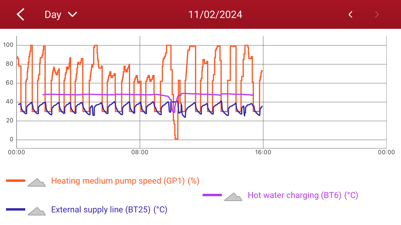
The cycling doesn’t seem to be as bad, but when there is a hot water demand, there are some elements of the chart I’m not sure about (see photo). However, I’m not running it on the Luxury comfort mode, so the hot water demand is less, so I’m not comparing like with like perhaps.
It does seem that for whatever reason the heat is not being lost from the flow. Flow and return are very close (can’t tell the difference on the graph?) for a DHW cycle but for a CH cycle the delta T is consistently around 5 degrees which is pretty normal.
I’m wondering what your charge pump is doing during a DHW cycle, is it pumping a little too fast for your set up and not giving chance to transfer the heat…I can’t recall if this can be changed for hot water only and I’m not at my unit to check. This can be plotted on the graph as a % demand.
That’s what I thought. So the Nibe buffer vessel is at the end of the heating loop. I assume your BT25 sensor isn’t located in the buffer tank (I couldn’t see any black wires in an earlier photo) and must be located somewhere on the CH flow after the red shuttle valve. This is just for interest and to complete the picture of what is where for your set up, your heating seems to be working well so it seems the set up is good.
Just to close off this line of enquiry, that’s all good; the “HP” signifies this is a Heat Pump compatible cylinder, and the detailed specs (2.028 m^2 of coil surface area, 0.2 bar of coil resistance) are OK.
That’s highly relevant and would appear to explain why you’re not getting the heat transfer to the DHW cylinder and why the BT12 alarm is triggering.
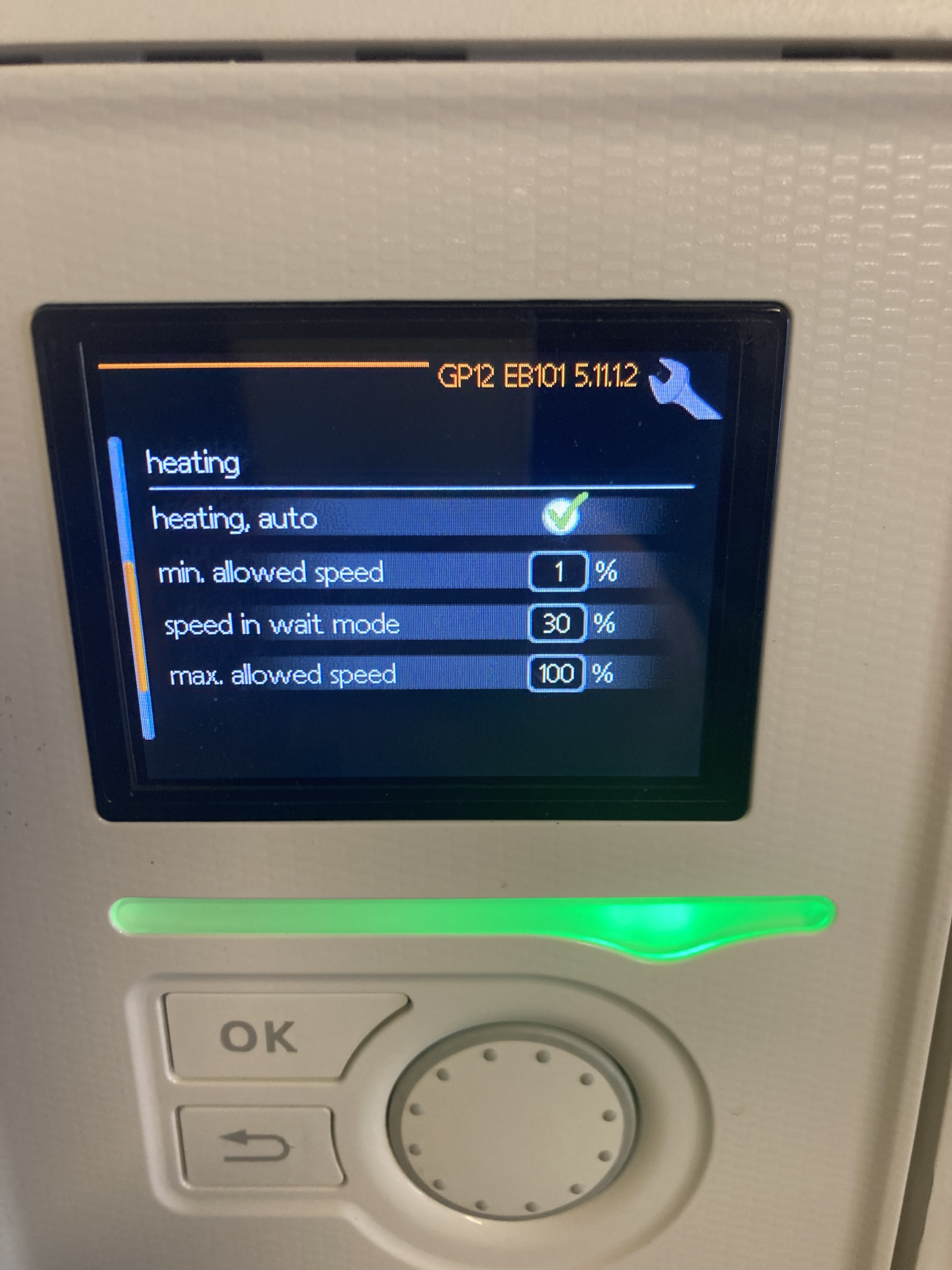
Could you check the Charge Pump speed settings in the Service Menu please?
As a short-term measure you might want to manually set the pump speed to e.g. 75% when in Hot Water mode.
Hi David. Are you able to explain why?..I’m not 100% understanding unless my knowledge is just wrong (very possible). A lower flow rate = increased chance to heat transfer? So in this case I immediately thought a lower charge pump speed would be better?
Looking at the data from my system, during a Hot Water cycle:
The Charge Pump speed varies a bit (confirming it’s under ‘automatic’ control) but it starts off at 64%, quickly dropping to 56% then holding steady at 52%
The Heat Meter shows a flow of about 1030 litres/hour (at 52%), which is 17 litres/min
The label from Katherine’s tank says it wants 15 litres/min (albeit at 80C)
My big concern was Katherine’s graph showing the Charge Pump speed down at 0% during a Hot Water cycle; that can’t be right (and would definitely explain the High Temperature alarm).